Sign In
Upload
Manuals
Brands
Sumitomo Manuals
DC Drives
CYCLO
Sumitomo CYCLO Manuals
Manuals and User Guides for Sumitomo CYCLO. We have
1
Sumitomo CYCLO manual available for free PDF download: Maintenance Manual
Sumitomo CYCLO Maintenance Manual (101 pages)
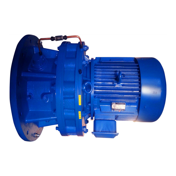
Gearmotor Reducer Drive for Servo Motors
Brand:
Sumitomo
| Category:
DC Drives
| Size: 9 MB
Table of Contents
Introduction: Safety Precautions
3
Table of Contents
4
Introduction: How to Refer to the Maintenance Manual, Table of Contents
4
For Gearmotor
5
Reading the Nameplates
5
Inspection Upon Delivery
5
For Reducer
6
Gear Unit Nameplate
6
Alarm Torque Nameplate
6
For Torque Limiter Equipped
6
Gearmotor, Reducer Nomenclature
7
Slow Speed Shaft Direction
7
Mounting Style
7
Able 1-1 SK Series Frame Sizes
8
Low Reduction Ratio Series Frame Sizes
8
Single Reduction Frame Sizes
8
Double Reduction Frame Sizes
8
Motor Nomenclature
9
Brake Type
9
Motor Capacity (Kw)
9
Storage Time
10
Internal Rust Prevention
10
Storage Location
10
Storage
10
Transport
11
Mounting Angle
12
Installation Location
12
Installation
12
When Load Condition Is Critical
13
Flange Type Assembly Issues
13
Tightening Torque for Nuts and Bolts for Ring Gear Housing
13
Construction Drawings
13
Keyless Shaft Motor Assembly Issues
14
Keyed Shaft Motor Assembly Issues
14
Checking Rotational Direction
15
Slow Speed Shaft Rotation Direction (Gearmotor)
15
Slow Speed Shaft Rotation Direction (Reducer)
15
Coupling with Other Machines
15
Mounting Connected Equipment
16
When Using a Coupling
16
When Using Chains, Sprockets, or Gears
16
When Using a V Belt
16
Wiring
17
Coordination of System Protection
18
Values for Insulation Resistance
18
Measuring Insulation Resistance
18
Removing and Attaching the Resin Terminal Box Cover
18
With Brake
19
Motor Wiring
19
Without Brake
19
High-Efficiency, 3-Phase Motor
20
Without Brake. 3-Phase Power Source
20
Premium-Efficiency, 3-Phase Motor
20
3-Phase Motor
20
Without Brake Inverter Drive
21
3 Lead Wires
21
6 Lead Wires
21
11 Lead Wires
21
3-Phase Power Source. Operates Rotating in One Direction.
22
8 Lead Wires
23
Direct On-Line Starting
23
Operates Rotating in One Direction
25
Plugging Operation
26
With Brake. 3-Phase Motor. Plugging Operation
27
With Brake Inverter Drive
30
Points to Note When Using a Quick Braking Circuit
34
Examples of Contact Point Connections with Quick Braking Circuits
34
Motorized Trochoid Pump Circuit Diagram
35
Structural Diagram of Machine with Motorized Trochoid Pump
35
Motorized Trochoid Pump Specifications
35
Wiring for Motorized Trochoid Pump Motor
35
Items to Check before Operation
36
Items to Check During Operation
36
Operation
36
Brake Torque and Activation Delay Time
37
Daily Inspection and Maintenance
38
Confirmation of Lubrication Method
39
Standard Lubrication Methods for Gear Units by Type
39
Maintenance Manual Pages
39
Allowable Oil Lubricant Viscosity
40
Recommended Lubricating Oil
40
Oil Change Interval
40
Oil Fill Quantity
41
Approximate Oil Fill Quantity (L)
41
Oil Fill Procedure
41
Oil Fill Procedure for Horizontal Type
41
Oil Fill Procedure for Vertical Type
42
Vertical Types
42
Draining Procedures
42
Draining Oil
42
Grease Replenishment Intervals
43
Recommended Grease
43
Double Reduction
44
Triple Reduction
44
Single Reduction
44
Grease Replenishment Quantity
44
Procedures for Filling and Discharging
45
Location of Grease Fill and Discharge Port
45
Grease Fitting with Metal Cap
45
Main Unit Maintenance
45
Motor Bearing Maintenance
46
Sealed Bearing Maintenance
46
Open Bearing Maintenance
46
Recommended Grease for Open Bearings
46
Procedures for Filling and Discharging Grease for Open Bearings
47
Open Bearing Unit Construction
47
Brake Maintenance and Inspection
48
Brake Construction and Gap Inspection and Adjustment
48
FB-01A1, FB-02A1, FB-05A1 (Indoor Type)
49
Gap Inspection
49
Gap Adjustment
49
FB-1D (Indoor Type)
50
FB-1E (Indoor Type)
51
FB-1HE, FB-2E (Indoor Type)
52
FB-3E, FB-4E (Indoor Type)
53
FB-5E, FB-8E (Indoor Type)
54
FB-10E, FB-15E (Indoor Type)
55
FB-20 (Indoor Type)
56
FB-30 (Indoor Type)
57
ESB-250, ESB-250-2 (Indoor Type)
58
Accessory Rectifier (DC Power Supply Unit)
58
Outline Drawing
58
Internal Circuit (Diagram)
58
Gap Adjusting Bar
59
Gap Adjusting Bar Dimensions
59
FB-01A1, FB-02A1, FB-05A1 (Outdoor Type)
60
FB-1D (Outdoor Type)
61
FB-1E (Outdoor Type)
62
FB-1HE, FB-2E (Outdoor Type)
63
FB-3E, FB-4E (Outdoor Type)
64
FB-5E, FB-8E (Outdoor Type)
65
FB-10E, FB-15E (Outdoor Type)
66
FB-20 (Outdoor Type)
67
FB-30 (Outdoor Type)
68
ESB-250, ESB-250-2 (Outdoor Type)
69
Changing the Brake Lining and Inner Disc
71
Brake Lining, Inner Disc Dimensions
71
Changing the V-Ring and Waterproof Seal (Outdoor Type)
71
Manually Releasing the Brake
72
FB Brakes (Excluding FB-20, FB-30)
72
Fb-20, Fb-30
72
When Brake Is Manually Released
73
One-Touch Release Lever Method
73
When Operating
73
Esb-250, Esb-250-2
73
Troubleshooting
74
Gear Unit Construction Drawings
76
Gear Unit, Principal Parts Single Reduction, Double Reduction
77
Gear Unit Construction Drawings (Triple Reduction)
78
Gear Unit Construction Drawings (SK Series)
80
Gear Unit Construction Drawings (Low Reduction Ratio Series)
80
Motor Unit Construction Drawing
81
Principal Parts of Motor
81
Application Product CYCLO Drive with Torque Limiter
83
Terminal Box·switch Box
84
Wiring for a Spring-Loaded Limit Switch
84
Limit Switch Wiring
84
Limit Switch Type (1-Point Signal, 2-Point Signal, 3-Point Signal)
84
Limit Switch Specifications
85
Example of How to Connect a Spring-Loaded Limit Switch
85
Rating
85
Contact Point Specification
85
Adjusting Preset Torque for the Spring-Loaded Limit Switch Model
86
Propriety to Adjust Preset Torque and Position of Adjusting Bolt
86
Adjusting Preset Torque
86
Lubricating Vertical Type, Frame Sizes 6130, 6135, 6140, 6145
87
Limit Switch
87
Oil Leakage
87
Torque Limiter, Daily Check
87
Daily Inspection and Maintenance
87
Checking the Torque Indicator
88
A-Type Torque Indicator
88
B-Type Torque Indicator
88
Torque Indicator
88
Type CHHM (Horizontal, Gearmotor), Triple Reduction
89
Construction Drawings
89
Torque Limiter Principal Parts
90
Torque Indicator Principal Parts
91
Torque Indicator Construction Drawings
91
Agitator Shaft Assembly
94
Coupling Bolts
94
Coupling with Other Machines
94
Allowable Bending Moment, Axial Load
95
Allowable Axial Load (N)
95
Base Unit Grease Replenishment
96
Daily Inspection, Maintenance
96
Gear Unit, Principal Parts (Models C14 – 28VM)
97
Gear Unit, Principal Parts (C3VM)
97
Construction Drawings
97
Warranty
98
Advertisement
Advertisement
Related Products
Sumitomo Cyclo HBB
Sumitomo Cyclo BBBH
Sumitomo Cyclo 6000
Sumitomo Cyclo BBB
Sumitomo Cyclo Helical Buddybox
Sumitomo CX32-10
Sumitomo CX33-12.5
Sumitomo CX34-10
Sumitomo CX42-25
Sumitomo CX44-20
Sumitomo Categories
Industrial Equipment
Engine
Cables and connectors
Inverter
Air Compressor
More Sumitomo Manuals
Login
Sign In
OR
Sign in with Facebook
Sign in with Google
Upload manual
Upload from disk
Upload from URL