Sign In
Upload
Manuals
Brands
Sugon Manuals
Server
I620-G20
Sugon I620-G20 Rackmount Server Manuals
Manuals and User Guides for Sugon I620-G20 Rackmount Server. We have
1
Sugon I620-G20 Rackmount Server manual available for free PDF download: User Manual
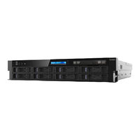
Sugon I620-G20 User Manual (155 pages)
Brand:
Sugon
| Category:
Server
| Size: 12 MB
Table of Contents
Trademark and Copyright
3
Operating Instruction for Power Supply
4
Dangerous Warning Statement
6
Table of Contents
9
List of Figures
12
List of Tables
18
1 System Overview
21
Product Features
21
Product Specification
23
Technical Specification
23
Table 1-1 I620-G20 Parameter Table (for Four Device Types)
23
Application Environment of Products
24
2 Architecture and Installation
24
Product Components
24
Table 1-3 Operation Environment of Products
24
Front Panel Component
25
Table 2-1 Description of Key Functions
26
Table 2-2 Description of Front Panel LED Indicator Function
26
Figure 2-2 Schematic Diagram of Reset Key
27
Figure 2-3 Schematic Diagram of Hard Disk Indicator
27
Table 2-3 Description of Hard Disk Rear Board Indicator
27
Rear Panel Component
28
Figure 2-4 Rear View of Product
28
Table 2-4 Interface Description of Rear Panel
28
Disassembly of Product Chassis and Main Components
29
Preparation Prior to Power on
29
Steps for Uncovering Server
30
Removing CPU
31
Figure 2-7 CPU Socket Schematic Diagram
32
Figure 2-8 Schematic Diagram for Opening CPU Locking Rod
32
Figure 2-9 Schematic Diagram for Opening CPU Protective Cover
32
Figure 2-10 CPU Installation
33
Removal Steps of CPU Heat Radiators
34
Figure 2-11 CPU Locking
34
Figure 2-12 Install CPU Heat Radiator
34
Memory Disassembly Steps
35
Table 2-5 Memory Installation Rule Table①
35
Hard Disk Disassembly Steps
37
Figure 2-13 Schematic Diagram of Memory Installation
37
Figure 2-14 Lock Hard Disk Box Fastener
37
Power Disassembly Steps
38
Figure 2-15 Pull out Hard Disk Box
38
Figure 2-16 Fix Hard Disk
38
Disassembly Steps of Expansion Cards
39
Figure 2-17 Press Locking Buckle
39
Figure 2-18 Plug out the Power Module
39
Disassembly Steps of Fan
40
Figure 2-19 Installation of Expansion Card
40
Installation Instruction of Guide Components
41
Figure 2-20 Fan Pull-Out Schematic Diagram
41
Figure 2-21 Guide Components
42
Figure 2-22 Fixing Position of Front Support of Sliding Rail
42
Figure 2-23 Pull out Internal Guide
43
Figure 2-24 Installation Method of Internal Rail
43
Figure 2-25 Install External Guide to Cabinet Upright Post
44
Figure 2-26 Upright Post Position Diagram
44
Figure 2-27 Install Machine Onto External Rail
45
Figure 2-28 Lock External Guide
46
Figure 2-29 Install the Chassis in Place and Lock It
46
3 Product Configuration
47
LCD Module
47
Typical Application
47
Function Description
47
Figure 2-30 Unlock Chassis
47
Inquiry and Operation of System-Related Information
48
Figure 3-1 LCD Display Module Layout Diagram
48
Table 3-1 Interface Description
48
Figure 3-2 LCD Principle Flowchart
49
Figure 3-3 Initial Interface
49
Figure 3-4 Display Mode of Fan Status
50
Figure 3-5 Display Mode of CPU Temperature Status
50
Figure 3-6 BMC IP Address Format
51
Figure 3-7 System Status
51
Eliminate CMOS Jumper Setting
52
Table 3-2 Failure Information Report
52
Table 3-3 CMOS Jumper Clearing Description
52
BIOS Setup
53
System BIOS Setup Method
53
Table 3-4 Description of Control Key
53
Main Menu
54
Figure 3-8 Main Menu Interface
54
Table 3-5 Description of Main Interface Parameters
54
Advanced Menu
55
Figure 3-9 Advanced Menu Interface
55
Table 3-6 Description of Advanced Interface Parameters
55
Figure 3-10 Benchmark Recommendation Setting Menu Interface
56
Figure 3-11 ACPI Settings Interface
56
Table 3-7 Description of Benchmark Recommendation Setting Interface Parameter
56
Figure 3-12 Wakeup Event Setup Interface
57
Table 3-8 Description of ACPI Settings Interface Parameters
57
Table 3-9 Description of Wakeup Event Setup Interface Parameters
57
Figure 3-13 Serial Port Console Redirection Interface
58
Table 3-10 Description of Serial Port Console Redirection Interface
58
Figure 3-14 (COM0) Console Redirection Settings Interface
59
Table 3-11 Description of (COM0) Console Redirection Settings
59
Figure 3-15 (EMS) Console Redirection Settings Configuration Interface
60
Table 3-12 Description of (EMS) Console Redirection Settings Configuration Interface
60
Figure 3-16 PCI Subsystem Settings Configuration Interface
61
Figure 3-17 Network Stack Configuration Interface
61
Table 3-13 Description of PCI Subsystem Settings Configuration Interface
61
Figure 3-18 CSM Configuration Interface
62
Table 3-14 Description of Network Stack Configuration Interface
62
Table 3-15 Description of CSM Configuration Interface
62
Chipset Menu
64
Figure 3-19 H/W Monitor Menu Interface
64
Figure 3-20 Chipset Menu Interface
64
Table 3-16 Description of H/W Monitor Interface Parameter
64
Table 3-17 Description of Chipset Interface Parameter
65
Figure 3-21 Processor Configuration Menu Interface
66
Table 3-18 Description of Processor Configuration Interface Parameters
66
Figure 3-22 Advanced Power Management Configuration Menu Interface
67
Table 3-19 Description of Advanced Power Management Configuration Interface Parameters
67
Figure 3-23 CPU P State Control Menu Interface
68
Table 3-20 Description of CPU P State Control Interface Parameter
68
Figure 3-24 CPU C State Control Menu Interface
69
Table 3-21 Description of CPU C State Control Interface Parameter
69
Figure 3-25 Common Refcode Configuration Menu Interface
70
Figure 3-26 QPI Configuration Menu Interface
70
Table 3-22 Description of Common Refcode Configuration Interface Parameter
70
Figure 3-27 QPI General Configuration Menu Interface
71
Table 3-23 Description of QPI Configuration Interface Parameter
71
Table 3-24 Description of QPI General Configuration Interface Parameter
71
Figure 3-28 QPI Status Menu Interface
72
Figure 3-29 Memory Configuration Menu Interface
72
Table 3-25 Description of Memory Configuration Interface Parameter
72
Figure 3-30 Memory Map Menu Interface
74
Figure 3-31 Memory RAS Configuration Menu Interface
74
Table 3-26 Description of Memory Map Interface Parameter
74
Table 3-27 Description of Memory RAS Configuration Interface Parameter
74
Figure 3-32 IIO Configuration Menu Interface
75
Table 3-28 Description of IIO Configuration Interface Parameter
75
Figure 3-33 IOAT Configuration Menu Interface
76
Figure 3-34 Intel VT for Directed I/O (VT-D) Menu Interface
76
Table 3-29 Description of IOAT Configuration Interface Parameter
76
Table 3-30 Description of Intel VT for Directed I/O (VT-D) Interface Parameter
76
Figure 3-35 PCH Configuration Menu Interface
77
Table 3-31 Description of PCH Configuration Interface Parameter
77
Figure 3-36 PCH Devices Menu Interface
78
Table 3-32 Description of PCH Devices Interface Parameter
78
Figure 3-37 PCH Ssata Configuration Menu Interface
79
Table 3-33 Description of PCH Ssata Configuration Interface Parameter
79
Figure 3-38 PCH SATA Configuration Menu Interface
80
Table 3-34 Description of PCH SATA Configuration Interface Parameter
80
Server Mgmt Menu
81
Figure 3-39USB Configuration Menu Interface
81
Figure 3-40 Server Mgmt Menu Interface
82
Figure 3-41 System Event Log Menu Interface
83
Table 3-37 Description of System Event Log Interface Parameter
83
Figure 3-42 BMC Self-Test Log Menu Interface
84
Table 3-38 Description of BMC Self-Test Log Interface Parameter
84
Figure 3-43 BMC Network Configuration Menu Interface
85
Table 3-39 Description of BMC Network Configuration Interface Parameter
85
Figure 3-44 View System Event Log Menu Interface
86
Figure 3-45 BMC User Settings Menu Interface
86
Table 3-40 Description of BMC User Settings Interface Parameter
86
Figure 3-46 Add User Menu Interface
87
Table 3-41 Description of BMC User Settings Interface Parameter
87
Figure 3-47 Delete Users Menu Interface
88
Table 3-42 Description of Delete User Interface Parameter
88
Security Menu
89
Figure 3-48 Change User Settings Menu Interface
89
Figure 3-49 Security Menu Interface
89
Table 3-43 Description of Change User Settings Interface Parameter
89
Table 3-44 Description of Security Interface Parameter
89
Boot Menu
90
Figure 3-50 Boot Menu Interface
90
Table 3-45 Description of Boot Interface Parameter
90
Save & Exit Menu
91
BMC Configuration
91
Figure 3-51 Save & Exit Menu Interface
91
Table 3-46 Description of Save & Exit Interface Parameter
91
Figure 3-52 Login Interface
92
Figure 3-53 User Entry Interface
92
Figure 3-54 Management Platform Items
92
Table 3-47 Description of Management Platform
92
Dashboard
93
Figure 3-55 Device Information Module
93
Figure 3-56 Network Information Module
93
Figure 3-57 Remote Console Module
94
Figure 3-58 Sensor Information Module (Part)
94
Fru & DMI
95
Figure 3-59 Event Log Module
95
Figure 3-60 FRU&DMI Sub-Menu
95
Figure 3-61 FRU Information Interface
96
Table 3-48 Description of Basic Information
96
Table 3-50 Description of Board Information
96
Table 3-51 Description of Product Information
96
Figure 3-62 DMI Information Interface
97
Table 3-52 Description of BIOS Information
97
Table 3-53 Description of System Information
97
Table 3-54 Description of Board Information
97
Server Health
98
Figure 3-63 Server Health Submenu
98
Figure 3-64 Sensor Reading Main Interface
98
Figure 3-65 Sensor List Area (Part)
99
Figure 3-66 Detailed Sensor Information Area
99
Table 3-55 Description of Temperature Sensor Threshold
99
Figure 3-67 Threshold Setup Interface
100
Figure 3-68 Sensor Event Statistics Diagram
100
Figure 3-69 Time Log Interface
101
Figure 3-70 System Log Interface
101
Component Information
102
Figure 3-71 Audit Log Interface
102
Figure 3-72 BSOD Screen Interface
102
Figure 3-73 CPU Information Display
103
Figure 3-74 Memory Information Interface
103
Table 3-56 Description of CPU Information
103
Table 3-57 Description of Memory Information
103
Figure 3-75 Onboard Hard Disk Information Interface
104
Table 3-58 Description of Onboard Hard Disk Information
104
Figure 3-76 Hard Disk Information Interface
105
Figure 3-77 Pcie Device Information Interface
105
Table 3-59 Description of Hard Disk Information
105
Table 3-60 Description of Pcie Device Information
105
Figure 3-78 PSU Information Interface
106
Figure 3-79 FAN Information Interface
106
Table 3-61 Description of PSU Information
106
Table 3-62 Description of FAN Information
106
Figure 3-80 Onboard NIC Information Interface
107
Figure 3-81 Expander NIC Information Interface
107
Table 3-63 Description of Onboard NIC Information
107
Table 3-64 Description of Expander NIC Information
107
Configuration
108
Figure 3-83 Active Directory Interface
108
Figure 3-84 Advanced Active Directory Setup Interface
109
Figure 3-85 Role Group Addition Interface
109
Table 3-65 Description of BIOS Information
109
Table 3-66 Description of Role Group Addition Interface
109
Figure 3-86 Advanced Audit Log Interface
110
Table 3-67 Description of Advanced Auditing Log Setup Interface
110
Figure 3-87 DNS Interface
111
Table 3-68 Description of DNS Setup Interface
111
Figure 3-88 LDAP/E-Directory Interface
112
Figure 3-89 Advanced LDAP Setup Interface
112
Table 3-69 Description of Advanced LDAP Setup Interface
112
Figure 3-90 Mouse Mode Interface
113
Figure 3-91 Management Network Setup Interface
114
Figure 3-92 Network Bonding Setup Interface
114
Table 3-70 Network Setup Interface Information
114
Figure 3-93 NTP Setup Interface
115
Figure 3-94 PEF Management Interface
115
Figure 3-95Event Filter Addition Interface -1
116
Figure 3-96Event Filter Addition Interface -2
117
Figure 3-99Alert Policy Addition Item Interface
118
Figure 3-100LAN Destination Addition Item Interface
119
Figure 3-101 RADIUS Interface
119
Figure 3-102 Remote Conference Interface
120
Figure 3-103 SMTP Interface
121
Table 3-79 Description of SMTP Interface Information
121
Figure 3-104 SSL Authentication Configuration Interface
122
Figure 3-105Generate SSL Item Interface
122
Table 3-80 Description of Generate SSL Interface Information
122
Figure 3-106 View SSL Item Interface
123
Figure 3-107 System and Audit Log Setup Interface
123
Table 3-81 Description of System and Audit Log Setup Interface Information
123
Figure 3-108 System Firewall Setup Interface
124
Figure 3-109 IP Address Policy Addition Interface
124
Figure 3-110 Port Policy Addition Interface
124
Figure 3-111 Advanced Setup Interface
125
Figure 3-112 Users Interface
125
Table 3-82 Description of User Information Item Addition
126
Remote Control
127
Figure 3-114Virtual Media Interface
127
Figure 3-115 User Lock Setup Interface
127
Figure 3-116 Remote Control Submenu
127
Figure 3-117Console Redirection Interface
128
Figure 3-118 Redirection Interface
128
Figure 3-119 Virtual Media Mounting Interface
129
Figure 3-120 Video Submenu
130
Figure 3-121 Keyboard Submenu
130
Figure 3-122 Keyboard Layout Submenu
131
Figure 3-123 Video Record Submenu
131
Figure 3-124 Video Recording Setup Interface
131
Figure 3-125 Power Submenu
132
Figure 3-126Power Control and Status
132
Table 3-83 Description of Power Option
132
Figure 3-127 Java SOL Interface
133
Figure 3-128 Serial Port Redirection Setup Interface
133
Table 3-84 Description of Serial Port Redirection Setup Interface
133
Figure 3-129 Session Submenu
134
Figure 3-130 ID Control Interface
134
Figure 3-131 Power Button Setup Interface
134
Auto Video Recording
135
Figure 3-132 Fan Policy Setup Interface
135
Figure 3-133 BIOS First Start Item Selection Interface
135
Figure 3-134 Automated Video Recording Submenu
135
Maintenance
136
Figure 3-135 Trigger Condition Setup Interface
136
Figure 3-136 Recorded Video List Interface
136
Figure 3-137 Maintenance Submenu
136
Table 3-85 Description of Trigger Condition
136
Figure 3-138 Setup Interface for Keeping Existing Configuration
137
Figure 3-139 Factory Setting Recovery Setup Interface
137
Firmware Update
138
Figure 3-140 Firmware Update Submenu
138
Figure 3-141 BMC Firmware Upgrade Interface
138
Figure 3-142 Selection Interface of BMC Firmware Upgrade and Refreshing Module
138
Figure 3-143 BIOS Firmware Refreshing Interface
139
Figure 3-144 BIOS Firmware Refreshing Alert Interface
139
4 OS Installation Guide
140
Windows 2008 Enterprise Server R2 SP1 64Bit
140
Red hat Enterprise Linux as 6 Update 2 X86_64
140
5 FAQ of Products
142
Appendix I Abbreviations
142
Appendix II POST Code Check Point of LCD
144
Appendix III RAID Configuration Description of Onboard Hard Disk Controller
151
Figure 0-1 POST Prompt Interface
151
Figure 0-2 RAID Management Interface
152
Figure 0-3 Controller Menu Interface
152
Figure 0-4 RAID Creation Interface
153
Figure 0-5 Hard Disk Selection
153
Figure 0-6 Advanced Setup Interface
154
Figure 0-7 Delete Virtual Drive
155
Figure 0-8 Delete Drive Group
155
Figure 0-9 Clear RAID Configuration Information
155
Advertisement
Advertisement
Related Products
Sugon TC6600
Sugon Categories
Server
Soldering Gun
More Sugon Manuals
Login
Sign In
OR
Sign in with Facebook
Sign in with Google
Upload manual
Upload from disk
Upload from URL