Sign In
Upload
Manuals
Brands
Suez Manuals
Measuring Instruments
Sievers M500e
User Manuals: Suez Sievers M500e Carbon Analyzer
Manuals and User Guides for Suez Sievers M500e Carbon Analyzer. We have
1
Suez Sievers M500e Carbon Analyzer manual available for free PDF download: Operation And Maintenance Manual
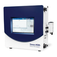
Suez Sievers M500e Operation And Maintenance Manual (325 pages)
Total Organic Carbon (TOC) Analyzer
Brand:
Suez
| Category:
Measuring Instruments
| Size: 40 MB
Table of Contents
Identification Records
3
Table of Contents
4
List of Tables
11
List of Figures
12
Confidentiality
13
Declaration of Conformity
13
Document Revision History
13
Trademarks and Patents
13
Standard Limited Warranty
14
Warnings
18
Chapter 1: Introduction
52
Chapter 2: System Description
53
System Specifications
53
System Overview
54
Sample Flow Path
55
Figure 2-1 Analyzer Schematic (Shown with Standard Ios)
55
Additional System Components
57
Microprocessor Controller and Electronics
57
Data Outputs
57
Chapter 3: Installation
58
Overview
58
Step 1: Unpack and Inspect the Analyzer
59
Figure 3-1 Interior Overview of the Analyzer
59
Packing List
60
Additional Installation Equipment
61
Step 2: Complete the Identification Records
62
Step 3: Select a Location for the Analyzer
62
Step 4: Install I/O Control Wiring (Optional)
63
Installing I/O Wiring
63
Working with Alarm Outputs (J1)
68
Table 3-1 Alarm Relay Outputs (J1)
68
Figure 3-2 Alarm Relay Output Detail
68
Working with 4-20 Ma Analog (J4) Outputs
69
Table 3-2 4-20 Ma Analog Outputs (J4)
69
Figure 3-3 Typical 4-20 Ma Circuit Applications
70
Working with Binary Inputs (Remote Start/Stop) (J2)
71
Table 3-3 Isolated State Inputs (J2)
71
Figure 3-4 Isolated State Input Circuit Detail
71
Figure 3-5 Instrument-Powered Isolated State Input Circuit Application
72
Figure 3-6 Externally-Powered Isolated State Input Circuit Application
72
Step 5: Install Power
73
Installing the AC Conduit
73
Step 6: Connect the Sample Inlet and Outlet Ports
77
Configuring the Sample Inlet and Outlet Ports
77
Step 7: Install the DI Water System
78
Using the Instrument Startup Wizard
78
Step 8: Install Ethernet and External Devices
87
Figure 3-7 Input and Output Connections
87
Installing a USB Connection for Data Transfer (Optional)
88
Installing a Serial Connection (Optional)
88
Table 3-4 I/O Panel 9-Pin Male D Connector
88
Installing an Ethernet Connection (Optional)
89
Figure 3-8 Asynchronous Serial Port (RS-232)
89
Step 9: Configure Basic Analyzer Settings
90
Enabling Analyzer Security (Optional)
90
Enabling Password Protection (Optional)
90
Configuring Local Settings
92
Setting the Measurement Mode
94
Figure 3-9 Measurement Mode Shown in Protocol Field
97
Configuring an Ethernet Connection
98
Enabling a PDF Printer
100
Setting up a Wireless Connection
102
Saving System Constants
104
Configuring the Data I/O
106
Chapter 4: Basic Analyzer Operation
111
Overview
111
Powering on and off the Analyzer
111
Figure 4-1 Home Screen When Password Protection Is Not Enabled
112
Figure 4-2 Home Screen When Password Protection Is Enabled
113
Recommended Operational State
114
The Ios System
114
Using the Standard Ios System
115
Using the Sample Inlet Block
115
Sievers M500E TOC Analyzer
115
Figure 4-3 the Standard Ios System
115
Steam Exposure
116
The Analyzer Screens
117
Navigating the Analyzer Screens
117
The Standard Toolbar
117
Printing and Exporting from the Analyzer Screens
120
The Home Screen
122
Figure 4-6 the Home Screen
122
Setting the Measurement Mode
124
Running Online Analysis
127
Running a Grab Sample
128
The Protocols Screen
130
Protocols Screen - Online Data Tab
130
Figure 4-7 Online Data Graphical View
130
Figure 4-8 Online Data Table View
131
Figure 4-9 Online Data Details
131
Protocols Screen - System Protocols and Grab Methods Data Tab
132
Figure 4-10 System Protocols and Grab Methods Data Tab
132
The Settings Screen
133
Settings Screen - System Setup Tab
133
Configuring Local Settings
133
Configuring Result Preferences
136
Setting Trend Graph Display Options
137
Configuring Export Preferences
138
Settings Screen - Instrument Settings Tab
140
Viewing System Constants
140
Saving System Constants
140
Printing and Exporting or System Constants
140
Importing System Constants
142
Settings Screen - Analyzer Settings Panel
143
Reviewing Analyzer Settings
143
Saving Analyzer Settings
144
Importing Analyzer Settings
145
Setting a User TOC Offset
146
Activating Options
147
Upgrading Firmware
148
Settings Screen - Hardware Tab
151
Configuring Alarm Outputs
152
Configuring 4-20 Ma Analog Outputs
154
Configuring Binary Input (Start/Stop)
155
Configuring an Ethernet Connection
157
Configuring the Flow Sensor
158
Enabling the DI Reservoir Level Sensor
160
Enabling the UV Lamp
161
Enabling a PDF Printer
162
Configuring a Wifi Connection (Optional)
164
Settings Screen - Consumables Tab
165
Entering and Reviewing Consumables Status
165
Settings Screen - Errors Tab
166
Settings Screen - Backup/Restore Tab
167
Backing up the Database
167
Scheduling Automatic Database Backups
169
Archiving the Database
171
Restoring a Backup
175
Restoring System Constants
176
The Data Screen
177
Reviewing Data History
177
The Password Protection Screen
182
The Help Screen
182
Chapter 5: Password Protection
183
Overview
183
Password Protection
183
Using Password Protection
183
Enabling Password Protection
183
Chapter 6: Calibration and System Protocols
186
Overview
186
Programming the TOC Autozero
187
To Program the TOC Autozero
187
Programming the TC/IC Conductivity Autozero
189
Required Calibration Supplies
190
Sievers M500E TOC Analyzer
191
Calibration Preparations
192
Saving System Settings
192
Performing Annual Maintenance Tasks
196
Handling Standards
196
Disable Automatic Backup
197
Protocol and Calibration Instructions
198
Ma Output Operation Verification Protocol (Optional)
199
TOC Single Point Calibration Protocol
204
Low Level TOC Single Point Calibration Protocol
208
TOC Multi-Point Calibration Protocol
212
TC/IC Conductivity Autozero Protocol
217
TOC Autozero Calibration Protocol
220
Accuracy & Precision Verification Protocol
223
Low Level Accuracy & Precision Verification Protocol
226
Reviewing Calibration and Verification History
229
Protocol and Calibration Worksheets
231
4-20 Ma Output Operation Verification (Optional) Worksheet
232
TOC Single Point Calibration Worksheet
233
Low Level TOC Single Point Calibration Worksheet
234
TOC Multi-Point Calibration Worksheet
235
TC/IC Conductivity Autozero Worksheet
236
TOC Autozero Worksheet
237
Accuracy & Precision Verification Worksheet
238
Low Level Accuracy & Precision Verification Worksheet
239
Chapter 7: Troubleshooting
240
Overview
240
Step 1: Visual Inspection
240
Inspecting Externally
240
Inspecting Internally
241
Step 2: Review Warnings and Errors
243
Reviewing Errors and Warnings
243
Warnings and Error Messages
246
3100-Unexpected DI Loop Level
246
3102-DI Flow on IC/TC Channel Not Detected
246
Step 3: Review Solutions for Basic Problems
247
The Analyzer will Not Power on
247
Checking the Sample Pump
247
No Sample Flow through the Analyzer
248
Confirm Flow of Water through the Measurement Module, DI Side
249
Additional Troubleshooting Steps
250
TC/IC Conductivity Autozero
250
TOC Autozero
250
TOC Offset
250
Problems Changing the Program Language
251
Problems with the DI Water Pump
253
Using the Diagnostics Menu
253
System Tests
255
Alarms
255
Analog Outputs
257
Modbus
258
Network Folder
259
Printer
260
Sample Flow Rate
260
IC Power Relay
261
Internet Connection
261
USB Serial Loopback
262
Serial Loopback
263
Wifi
263
Export Diagnostics
264
Service Diagnostics
265
Level 1 Diagnostics
266
Step 4: Contact Technical Support
266
Step 5: Return the Analyzer to SUEZ
267
To Prepare Analyzer for Shipping
267
Draining the Sample Side
267
Draining the DI Loop
271
Chapter 8: Maintenance
274
Replacing Consumables and Maintenance Items
274
Table 8-1 Replacement Schedule for Consumables
275
Figure 8-1 Interior Overview of the Analyzer
275
Verifying the DI Water Level
276
Sievers M500E TOC Analyzer
276
Replacing the UV Lamp
278
Replacing the Sample Pump Heads
280
Replacing the Resin Cartridge
282
Replacing the In-Line Filter Element
285
Replacing the Fan Filter
286
Entering New Consumables Installation Dates
287
Cleaning the Analyzer
288
Table 8-2 Sievers M500E TOC Analyzer 3-Year Maintenance Worksheet
288
Appendix A: Analyzer Dimensions
290
Analyzer Dimensions
290
Analyzer Configured with Standard Ios
291
Figure A-1 Analyzer Dimensions, with Standard Ios System
291
Figure A-2 Right-Side Analyzer Dimensions, with Standard Ios System
292
Figure A-3 Left-Side Analyzer Dimensions, with Standard Ios System
293
Analyzer Configured with Sample Inlet Block
294
Figure A-4 Analyzer Dimensions, with Sample Inlet Block
294
Figure A-5 Right-Side Analyzer Dimensions, with Sample Inlet Block
295
Figure A-6 Left-Side Analyzer Dimensions with Sample Inlet Block
296
Appendix B: Streaming Data
297
Data-Streaming Methods
297
To Stream Data Via a Serial (RS-232) Port
297
To Stream Data Via Ethernet
298
Determining Your Communications Port Number
299
Appendix C: Warning and Error Descriptions
300
Appendix D: DI Water Installation Details
308
Additional DI Water Installation Details
308
Installing the Resin Cartridge
308
Rinsing the Analyzer
313
Appendix E: Modbus with the Analyzer
315
The Ethernet Connection and Modbus
315
Enabling Modbus
315
Testing Modbus for the Analyzer
316
The Modbus Register Table
316
Table E-1 Modbus Register Table
317
Index
322
Advertisement
Advertisement
Related Products
Suez Sievers M500
Suez Sievers 500 RLe
Suez Sievers UPW Boron Analyzer
Suez Categories
Measuring Instruments
Water Pump
Accessories
Transmitter
Water Filtration Systems
More Suez Manuals
Login
Sign In
OR
Sign in with Facebook
Sign in with Google
Upload manual
Upload from disk
Upload from URL