Sign In
Upload
Manuals
Brands
STREBEL Manuals
Boiler
S-CB+400
STREBEL S-CB+400 Manuals
Manuals and User Guides for STREBEL S-CB+400. We have
1
STREBEL S-CB+400 manual available for free PDF download: Installation Operating & Maintenance Manual
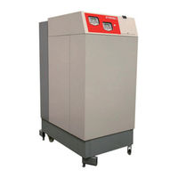
STREBEL S-CB+400 Installation Operating & Maintenance Manual (128 pages)
Boiler Range
Brand:
STREBEL
| Category:
Boiler
| Size: 5 MB
Table of Contents
Table of Contents
3
Introduction
6
1 Safety Guidelines
6
2 Technical Data S-Cb
7
400 And S-Cb
7
Introduction
7
Technical Specifications Datasheet
8
Erp Specification Datasheet
10
Safety Measures for Preventing Internal Flue Gas Recirculation
11
Benefits of the S-Cb + 400 & 550 Boiler
11
Description of the most Important Boiler Parts
12
3 Technical Dimensions of the S-Cb
13
S-Cb + 550
13
4 Accessories and Unpacking of the Boiler
14
Accessories
14
Unpacking
14
5 Installation of the S-Cb
15
General Notes
15
General
15
Oiler Room
15
Boiler Room
15
Ventilation
16
Removing the Top, Front and Side Panels
16
5.4 Mounting the Boiler
17
6 Connections Water Side
17
Boiler Connections
17
Condensate Drain Connection
18
Flow and Return Connections
18
The Expansion Vessel
18
Pressure Relief Valve
19
Bypass
19
Pump Functionality
19
Frost Protection
19
Installing a Strainer And/Or Dirt Separator
20
Water Quality
20
Plastic Piping in the Heating System
21
Automatic Air Vent
21
Automatic Water Filling Systems
21
Water Pressure
21
Chemical Water Treatment
22
Under Floor Heating
22
Flush the System with Fresh Water
22
Installation Examples
22
550 CH Boiler
22
Installation Containing Two S-Cb
23
400/550 CH Boilers Using NON-RETURN Valves
23
7 Hydraulic Graphs
24
8 Flue Gas and Air Supply System
25
General
25
Flue Gas System
25
Boiler Categories - Types of Flue Gas Systems
26
C63 Certified
27
Flue Terminal
28
Vertical Flue Terminal Positioning
28
Common Flue / Ducts
28
Air Supply
28
Air Quality
28
Air Supply through Humid Areas
28
Pipe Heights and Mutual Distances on a Flat Roof
29
S-Cb 400
30
Flue Gas and Air Supply Resistance Table - Concentric Parts
30
Air Inlet / Flue Gas Outlet Calculation Examples
30
Twin Pipe Flue Gas and Air Supply Resistance Table
31
Example A: Twin Pipe System
32
Example B: Single Pipe System for Flue Gas Outlet Only
33
Example C: Twin Pipe System with Wall Mounted Air Duct
34
Example D1: Twin Pipe System with Concentric Roof Terminal
35
Example D2: Twin Pipe System with Concentric Roof Terminal
36
Separate Air Supply and Flue Terminal for a Pitched Roof
37
Separate Air Supply and Flue Terminal for a Flat Roof
37
Electrical Installation
38
General
38
Connections
39
Cascaded Connection Including Shielding
39
Connecting the Power Supply and Boiler Pump P1, 230V/1
40
Fuses
41
List for Connections
41
Sensors
43
Electrical Circuit Diagram Top Burner (PCB A, Left)
44
Electrical Circuit Diagram Bottom Burner (PCB B, Right)
46
10 User Interface
48
Control Panel / Display Unit
48
Menu Structure
49
Display During Operation
51
Monitor Screens
52
Service Function
54
Schornsteinfeger Function
55
Programming in Standby Mode
56
Setting the Time & Date
56
Set Points
57
10.10 Setting the Timer Programs
58
10.11 Setting the Outdoor Specifications
61
Parameters for Setting the Outdoor Graph
61
Outdoor Graph - Main Settings
62
Outdoor Graph - Additional Settings
63
Display
64
10.12 Checking the Operating History
65
10.13 Checking the Fault History
66
10.14 Setting the Maintenance Specifications
67
10.15 Setting the User Lock
70
10.16 Setting the Parameters at the Control Panel
71
10.17 Fault Codes Display
78
Lock-Out Codes
78
Blocking Codes
80
Important Message
81
11 Controlling Options and Settings
82
General
82
Extra Boiler Control
82
Max Cooling Time
82
Temperature Display On/Off
82
Water Pressure
82
Gas Type Selection
82
Soft Start Option
83
Pump Mode (EC Technology)
83
Heating
84
Controlling Behaviour Settings
84
Room Thermostat On/Off
84
Room Thermostat OPENTHERM
85
Outside Temperature Related Flow Control
85
VDC Remote Flow Temperature Set Point
85
VDC Remote Burner Input Control
86
Timer Contact Function
86
Indirect Hot Water / Calorifier
87
Pump and 3-Way Valve Control
87
Tank Thermostat
87
Tank Sensor
87
Low/High Flow Temperature to Tank Coil
88
Heating and Hot Water Switching Time
89
Heating and Hot Water Switching Time at a Sudden Temperature Drop
89
Anti-Legionnaires' Disease (Pasteurisation) Function
90
Cascade Control
91
Parameter Settings for Cascaded Boilers
91
Monitor Screens
93
Output Control and Burner Sequence
93
12 Commissioning the Boiler
94
First: Flushing the Boiler with Water
94
Second: Filling & Venting the Boiler and the System
94
Third: Check the Water Flow
94
13 Starting the Boiler
96
General
96
Firing for the First Time
97
14 Adjusting and Setting the Burners
98
Introduction
98
Adjustment Tables
98
Adjustment Values
98
Gas Valve Setting Screws: Drawing
100
How to Remove and Mount the Flue Plug
101
Adjustment Actions: General Scheme
102
Note: CO 2 Measuring Position
103
Adjusting in Case of a New Boiler, or after Maintenance (Case A)
103
General Remark
103
Checking and Adjusting the Bottom Burner
104
Checking both Burners
104
Adjusting after Gas Valve Replacement or in Case of Gas Conversion (Case B)
105
General Remarks
105
Case Badjustments
105
Setting Parameter P4BD Gas Type (Display D8)
106
15 Putting the Boiler out of Operation
107
16 Fault Codes, Blocking Codes
108
Fault Codes
108
Blocking Codes
115
Maintenance Attention Message
119
17 Maintenance
120
General
120
Inspection & Maintenance
120
18 User Instructions
123
19 Examples of Installations
124
Advertisement
Advertisement
Related Products
STREBEL S-CB+550
Strebel S-CBX 125
Strebel S-CBX 155
Strebel S-CB+ Series
Strebel S-CB+100
Strebel S-CB+120
Strebel S-CB 60
Strebel S-CB 80
Strebel S-CB 120
Strebel SC-B
STREBEL Categories
Boiler
Heat Pump
Water Heater
More STREBEL Manuals
Login
Sign In
OR
Sign in with Facebook
Sign in with Google
Upload manual
Upload from disk
Upload from URL