Sign In
Upload
Manuals
Brands
Stratus Manuals
Server
ftServer 4500
Stratus ftServer 4500 Manuals
Manuals and User Guides for Stratus ftServer 4500. We have
1
Stratus ftServer 4500 manual available for free PDF download: Operation And Maintenance Manual
Stratus ftServer 4500 Operation And Maintenance Manual (114 pages)
Brand:
Stratus
| Category:
Server
| Size: 1 MB
Table of Contents
Table of Contents
3
Notation Conventions
9
Preface
9
Getting Help
11
1 Overview of Ftserver 2600, 4500, and 6300 Systems
15
System Features
15
System Design
15
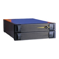
Figure 1-1. Ftserver 2600, 4500, and 6300 Systems
16
CPU-I⁄O Enclosures: Front
17
Figure 1-2. Ftserver 2600, 4500, and 6300 Systems: Front View
18
CPU-I/O Enclosures: Rear
19
Figure 1-3. Ftserver 2600, 4500, and 6300 Systems: Rear View
19
Table 3-3. Power Supply LED
19
Figure 1-4. CPU-I/O Enclosure: Interior Components, Model 2600
20
Interior Components
20
Figure 1-5. CPU-I/O Enclosure: Interior Components, Models 4500 and 6300
21
Description of System Components
22
Peripheral Components
24
System Crus
24
Table 1-1. Customer-Replaceable Units
24
2 Hardware Operation
25
Standby Power
25
System Power
26
Starting up the System
26
Shutting down the System
27
Fan Speed
28
3 Troubleshooting the Hardware
29
Information about Troubleshooting
29
System Administration Documentation
30
Status Leds and System Buttons
30
System Front Panel Leds
32
Figure 3-1. System Front Panel Leds
32
CPU-I/O Enclosure Status Leds
33
Table 3-1. System Front Panel Leds
33
Figure 3-2. CPU-I/O Enclosure Leds and Buttons (Bezel Removed)
34
Table 3-2. CPU-I/O Enclosure Leds
35
Buttons on the CPU-I/O Enclosure
36
Memory Fault Leds
36
Leds on the Back of the CPU-I/O Enclosure
37
Hard Disk Drive Status Leds
38
Figure 3-3. Hard Disk Drive Leds
38
Table 3-4. Hard Disk Drive Leds
38
Ethernet and VTM Port Leds
38
Ethernet and VTM Port Leds
40
Figure 3-4. Ethernet and VTM Ports: Status Leds
41
Modem Assembly: Status Leds
42
Table 3-5. Ethernet Port and VTM Port Activity LED States
42
Table 3-6. Ethernet Port and VTM Port Connection Speed LED States
42
Figure 3-5. Modem Assembly: Status Leds
43
Table 3-7. Modem Assembly: LED States
44
Power Distribution Unit Status Leds
45
Figure 3-6. PDU Status Leds
45
Table 3-8. Model AA-P87600 PDU Status Leds
46
General Hard Disk Drive Problems and Solutions
47
Table 3-9. Troubleshooting Disk Drives
47
DVD Drive Problems and Solutions
48
Using the NMI Button to Create a Dump File
49
Table 3-10. Troubleshooting the DVD Drive
49
4 General Servicing Information
53
Unpacking Crus
53
Storing Crus
54
Figure 4-1. Shipping Impact Indicators
54
Repacking Crus
55
Replacing a CRU
55
General Safety Precautions
56
5 Installing and Replacing System Components
57
Before Replacing Crus
58
Removing the Bezel
60
Figure 5-1. Replacing the System Bezel
61
Removing and Replacing a Front Panel
62
Figure 5-2. Replacing the Front Panel
63
Removing and Replacing a CPU-I/O Enclosure
64
Figure 5-3. Disconnecting a CPU-I/O Enclosure
65
Figure 5-4. Loosening the Front Release Levers on an Enclosure
66
Figure 5-5. Disengaging the Safety Lever on an Enclosure
67
Figure 5-6. Aligning the CPU-I/O Enclosure
69
Figure 5-7. Engaging the Release Levers on an Enclosure
70
Removing and Replacing a CPU-I/O Enclosure Cover
71
Figure 5-8. Removing an Enclosure Cover
72
Figure 5-9. Replacing an Enclosure Cover
73
Removing the Plenum
74
Replacing the System Backplane Assembly
75
Figure 5-10. Replacing the Plenum
75
Figure 5-11. Replacing the System Backplane Assembly
78
Replacing and Adding Dimms
80
Figure 5-12. DIMM Slot Numbering in Single-Processor Systems (Viewed from Front)
81
Figure 5-13. DIMM Slot Numbering in Dual-Processor Systems (Viewed from Front)
82
Figure 5-14. DIMM Ejector Levers
84
Table 5-1. Memory Fault Leds
85
Removing and Replacing the CPU-I/O Enclosure Fan Assembly
86
Figure 5-15. Replacing the CPU-I/O Enclosure Fan Assembly
87
Removing and Replacing the Power Supply Fan
88
Figure 5-16. Removing the Power Supply Fan
89
Removing and Installing a Low-Profile PCI Adapter
90
Figure 5-17. Replacing a Power Supply Fan
90
Figure 5-18. Removing the PCI Adapter Bracket
92
Figure 5-19. Removing the PCI Adapter from the PCI Slot
93
Replacing a PCI Riser Assembly and Its Adapters
94
Figure 5-20. Removing the PCI Bulkhead Bracket Screws
95
Figure 5-21. Loosening the Captive Screw on the Motherboard
96
Figure 5-22. Removing the Bracket from the PCI Riser Assembly
97
Figure 5-23. Removing an Adapter from the Connector on the PCI Riser
98
Figure 5-24. Inserting a Full-Height Adapter into the PCI Riser
99
Removing and Inserting an Internal Hard Disk Drive
100
Figure 5-25. Replacing a Disk Drive
101
Removing and Replacing a DVD Drive
102
Figure 5-26. Replacing a DVD Drive
103
Replacing or Installing a Modem Assembly
104
Figure 5-27. Replacing the Modem Assembly
105
Figure 5-28. Removing the Metal Plate over the Modem Connector
106
Removing and Replacing a PDU
107
Figure 5-29. Replacing a PDU
108
Advertisement
Advertisement
Related Products
Stratus ftServer 4900 Series
Stratus ftServer 4410
Stratus ftServer 4400
Stratus ftServer T30
Stratus ftServer 2600
Stratus ftServer 6300
Stratus ftServer W 2300Series
Stratus ftserver 3300
Stratus ftserver 5600
Stratus ftserver 6600
Stratus Categories
Lifting Systems
Server
Scissor Lifts
Receiver
PCI Card
More Stratus Manuals
Login
Sign In
OR
Sign in with Facebook
Sign in with Google
Upload manual
Upload from disk
Upload from URL