Sign In
Upload
Manuals
Brands
Steris Manuals
Laboratory Equipment
SYSTEM 1E
Steris SYSTEM 1E Manuals
Manuals and User Guides for Steris SYSTEM 1E. We have
1
Steris SYSTEM 1E manual available for free PDF download: Maintenance Manual
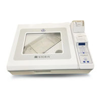
Steris SYSTEM 1E Maintenance Manual (179 pages)
Liquid Chemical Sterilant Processing System
Brand:
Steris
| Category:
Laboratory Equipment
| Size: 7 MB
Table of Contents
Table of Contents
6
Section Description Page
7
Safety Precautions
13
Safety Precautions Summary
13
Symbol Definitions
16
Table 1-1.Symbol Definitions
16
General Information
17
Technical Specifications
17
Overall Size SYSTEM 1E Liquid Chemical Sterilant Processing System
17
Weight
17
Utility Requirements Electrical
17
Water Requirements
17
Pre-Filter Specifications
17
Environmental Conditions
17
General Installation Location Recommendation
17
Figure 1-1. Processor Placement
17
Installation Checkout Procedure
18
Purpose
18
General Guidelines
18
Distribution
18
Procedure
18
Electrical Utilities
18
Water Inlet
18
Fill Times
19
Drain
19
Verification
19
Return Materials Authorization Procedure
20
Shipping Precautions
20
Draining the SYSTEM 1E Liquid Chemical Sterilant Processing System Prior to Shipment
20
Boxing Procedure
20
Service Mode Procedures
21
General
21
Variable Names
21
How to Access Service Mode
21
Figure 2-1. Maxpure Filter Alert Printout
21
Figure 2-2. Service Mode Information Printout
21
Table 2-1.Variable Names
21
Service
22
MFG (Manufacturing)
22
Check
22
Figure 2-3. Service Mode Program Tree
22
Sf Hold
24
Air Test
24
Battery
25
Tests
25
Valves
25
Input
26
Console
26
Keypad
26
Dip Sw (Dip Switch)
27
Display
27
More
27
Hpp Test
28
Diagval (Diagnostic Values)
28
Figure 2-4. Diagnostic Cycle Parameters
28
Lists
29
History
29
Values
29
Calibration
30
Figure 2-5. Setup
30
Pressure Calibration
31
Temperature Calibration
31
Figure 2-6. Pressure Calibrated Values
31
Figure 2-7. Temperature Calibrated Values
32
Concentration Probe Calibration (Conc)
33
Uv Sensor Calibration
34
Figure 2-8. Concentration Probe Calibration
34
Default Calibration
35
Restore Calibration Data
36
View
36
Print
36
Enhanced Operator Mode
37
Figure 2-9. Calibration Data Printout
37
Figure 2-10. Cycle Data Printout
37
Enhanced Operator Mode Print-Outs
38
Burn-In SYSTEM 1E Liquid Chemical Sterilant Processing System
38
How to Exit Service Mode
38
Principles of Operation
39
SYSTEM 1E™ Liquid Chemical Sterilant Processing System Description
39
Overview of the System
39
Component Description
39
Fluid Pathway Description of SYSTEM 1E Processor
39
Table 3-1.Component List
40
Figure 3-1. General Components
41
Water Filter Housing Description
42
Air Manifold Description
43
Principles of Operation - Liquid Chemical Sterilization Processing Cycle Description
43
Principles of Operation - Diagnostic Cycle Description
45
Control
47
Control Assembly
47
Control Board
47
Interface Box Assembly
48
Pressure Transducer
48
Electrical Description
48
High-Pressure Pump Test Routine
48
General
48
Diagnostic HP Pump Test
48
Inspection and Maintenance
49
General
49
Daily Maintenance of SYSTEM 1E ™ Liquid Chemical Sterilant Processing System
49
Figure 4-1. Clean SYSTEM 1E Processor External Surfaces
49
Figure 4-2. Open Lid
49
Figure 4-3. Clean Tray for Processing
49
Figure 4-4. Clean Flexible Tray
50
Figure 4-5. Clean Flexible Tray
50
Figure 4-6. Check Drain Screen
50
Figure 4-7. Clean Drip Pan
50
Preventive Maintenance Schedule
51
Figure 4-8. Check Printer Paper Supply and Ribbon, Verify Print Quality
51
Table 4-1. Preventive Maintenance Schedule
51
Troubleshooting
53
Section Description Page
53
Section Description Page
54
Liquid Chemical Sterilization Cycle Faults
55
Wait for UV
55
Temperature under 43°C
55
UV Intensity Timeout
55
Liquid Chemical Sterilization Processing Cycle Faults
55
Fill Problem
56
Heat Problem
56
Temperature under 45.5°C
56
Concentration Low
57
Chamber Level Low
57
Heater Problem
57
Chamber Open
57
Temperature over 60°C
58
UV Lamp Problem
58
Maxpure™ Filter Test Failed (A. Without and B. with Numbers)
58
Temperature Problem
58
Power Failure
59
HP Pump Failure
60
Diagnostic Cycle Faults
61
A/D Converter Fault
61
Inlet H2O Temp < 43°C
61
UV Intensity Timeout
61
UV Lamp below 14.5 Ma
61
Fill Time > 5 Minutes
62
Pressure Transducer Fault
62
Circulation Pressure Low
62
Thermocouple Failed
63
Circulation Valve Fault
63
Heat Rate Low
63
Drain Valve Fault
63
Drain Time Fault
63
Concentration Monitor Failed
64
Concentration Monitor Failed (Cont.)
65
Maxpure Filter Membrane Fault (A. Without Numbers and B. with Numbers)
65
Drain Check Fault
66
Ambient Temperature Fault
66
Lid Open Fault
66
HP Pump Fault
66
Other Faults
67
Ground Fault Interrupt (GFI) Trip
67
Water Spills from SYSTEM 1E Processor
67
Control Faults
68
Printer Prints: ROM FAILURE
68
Printer Prints: RAM FAILURE
68
Printer Prints: RTC FAILURE
68
Printer Prints: TC1 FAILURE
68
Printer Prints: TC2 FAILURE
68
Printer Prints: TC3 FAILURE
69
Printer Prints: CHM-PRES NOT CALIBRATED
69
Printer Prints: INLET NOT CALIBRATED
69
Printer Prints: OUTLET NOT CALIBRATED
69
Printer Prints: DRN-BLK NOT CALIBRATED
69
Printer Prints: CONC. NOT CALIBRATED
69
Printer Prints: FLASH VALUES RESTORED
69
Printer Prints: FLASH VALUES SAVED
70
Printer Prints: FLASH VALUES LOST. PLEASE REPROGRAM
70
Printer Prints: **LOW BATTERY** PLEASE REPLACE
70
Printer Prints: KEY X ERROR
70
Cable/Harness Pin Outs
70
Figure 5-1. Transducer Harness Assembly (P6) Pin out Locations
70
Figure 5-2. Analog Cable Assembly - Pin out Locations
71
Figure 5-3. DC Input Harness - Pin out Locations
72
Figure 5-4. DC Power Harness - Pin out Locations
72
Figure 5-5. AC Output Harness - Pin out Locations
73
Figure 5-6. Serial Port Harness - Pin out Locations
73
Figure 5-7. DC Power Supply Harness - Pin out Locations
74
Field Test Procedure
75
General
75
Test Instrumentation
75
Installation Verification
75
Test Procedures
75
Pressure Transducer Calibration
75
Temperature Calibration
75
Concentration Monitor Calibration
75
UV Monitor Calibration
75
HP Pump Flow Rate and Pressure Test
75
LS6 Switch Test Procedure
76
Seal Leak Test and Compressor Output Test
76
Pressure Hold Test for Housing of Maxpure™ Filter
76
CK8 Test
77
Output Test
77
Touch Pad Test
77
Console
77
Keypad
77
Component Repair and Replacement
78
Lid Replacement/Shimming Procedure
78
Figure 7-1. Adjust Lid Latch
78
Lid Switch and Latch Flag Adjustment Procedure
79
Drip Pan Assembly Replacement
80
Figure 7-2. Lid Latch Hook Adjustment
80
Figure 7-3. Lid Latch Flag Adjustment
80
Figure 7-4. Disconnect Quick Disconnect Seal Coupler
80
Figure 7-5. Remove Seal Retaining Bars
81
Figure 7-6. Use Drogue Tools to Remove Drogues from Drip Pan
81
Figure 7-7. Remove Printer Cover
81
Figure 7-8. Remove Hose
81
Aspirator Assembly Leak Test Procedure
82
Figure 7-9. Loosen Control Hinge Screws
82
Figure 7-10. Loosen Gas Spring Setscrew
82
Figure 7-11. Remove Gas Spring Clevis Pin
82
Adapter Tray Leak Check Procedure
83
Lid Seal Sanding Procedure
83
Seal Replacement Procedure
84
Pinch Valve Sleeve Replacement Procedure
84
Figure 7-12. Connect Quick Disconnect Coupler
84
Figure 7-13. Press Seal in Place Using allen Wrench Elbow
84
Concentration Probe Cleaning
85
Seal Pressure Regulator/Compressor Output Test
85
Power Supply
85
Figure 7-14. Pinch Valve Gap Adjustment
85
Connector Board
86
Control Board
86
Program Chip Change
86
Display
87
Printer
87
Pressure Transducer
87
Paper Roll and Ink Cartridge Replacement Procedure
88
Changing Maxpure™ Filter
90
Changing Sterile Air Filter
93
Changing Pre-Filters Procedure
94
Figure 7-15. Pre-Filter Arrangement
94
Ultra Violet (UV) Water Treatment System
95
Figure 7-16. Ultra Violet Water Treatment System (Catalog # A1579)
95
Figure 7-17. Aquafine STERIUV5 Control Panel
96
UV Monitor Replacement
97
Figure 7-18. Loosen Brass Nut
97
Figure 7-19. Install O-Rings
97
UV Lamp Replacement
98
Figure 7-20. Unthread Sensor Nipple
98
Figure 7-21. Remove Sensor Sleeve
98
Figure 7-22. O-Ring and Quartz Hi-Hat
98
Figure 7-23. Remove Screws from Shroud Cover
98
Figure 7-24. Remove Wire Form
99
Figure 7-25. Remove UV Lamp Shroud
99
Figure 7-26. Remove UV Lamp Slowly
99
Figure 7-27. Install New UV Lamp
100
Figure 7-28. Lock Lamp Socket with Wire Form
100
Figure 7-29. Install Shroud Cover
100
UV Quartz Sleeve Replacement
101
Figure 7-30. Remove Quartz Sleeve Bolt
101
Figure 7-31. Remove Fan Assembly
101
Figure 7-32. Remove Quartz Sleeve Bolt (Opposite End)
101
Figure 7-33. Free Quartz Sleeve
102
Figure 7-34. Inspect O-Rings and Quartz Sleeve
102
Figure 7-35. Place Wet O-Ring on Quartz Tube
102
Figure 7-36. Install Shroud Plate and Quartz Sleeve Bolt
102
UV Power Supply Fuse Replacement
103
Figure 7-37. Install Opposite-End Quartz Sleeve O-Ring
103
Figure 7-38. Lock Shroud with Pan-Head Screw
103
Figure 7-39. Fuse Door Location
103
Reset UV Lamp Elapse-Time Meter
104
Convert Fan from Vertical to Horizontal Mounting Configuration
104
Figure 7-40. Convert Fan from Vertical to Horizontal Mounting
104
Figure 7-41. Remove and Discard Heat Sink
105
Figure 7-42. Remove 10-24 X 3/4" Pan Head Screw
105
Figure 7-43. Install Fan Mounting Bracket
105
Figure 7-44. Re-Install Sleeve Locking Screw
105
UV Lamp Socket Grounding
106
Figure 7-45. Install Fan Cover and Secure with Screws
106
Figure 7-46. Ensure Lamp Socket Is Grounded
106
Advertisement
Advertisement
Related Products
Steris Reliance 1024
Steris Reliance 1034
Steris SYSTEM 1 endo
Steris AMSCO 600 Medium 1063V-3
Steris 10009192
Steris Vision 1300 Series
Steris Vision 1321
Steris Vision 1330L
Steris Reliance 1227
Steris RELIANCE 120 Series
Steris Categories
Medical Equipment
Laboratory Equipment
Washer
Monitor
Lighting Equipment
More Steris Manuals
Login
Sign In
OR
Sign in with Facebook
Sign in with Google
Upload manual
Upload from disk
Upload from URL