Sign In
Upload
Manuals
Brands
ST Manuals
Microcontrollers
UM2966
User Manuals: ST UM2966 Asset Tracking
Manuals and User Guides for ST UM2966 Asset Tracking. We have
1
ST UM2966 Asset Tracking manual available for free PDF download: User Manual
ST UM2966 User Manual (86 pages)
Brand:
ST
| Category:
Microcontrollers
| Size: 3 MB
Table of Contents
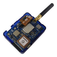
Figure 1. STEVAL-ASTRA1B Development Kit
1
Getting Started
2
Precautions for Use
2
Features
2
Kit Components
2
Table 1. Precautions for Use
2
STEVAL-ASTRA1SB System on Board
3
Figure 2. STEVAL-ASTRA1B Components and Assembly
3
Figure 3. Block Diagram of the STEVAL-ASTRA1SB System on Board
4
Figure 4. System on Board - Main Component Placement and Pinout
5
Figure 5. Solder Jumpers for Remapping
5
Table 2. System on Board - Edge Pinout
6
Table 3. System on Board - Bottom Pinout (from B1 to B68)
7
Table 4. System on Board - Bottom Pinout (from B69 to B110)
9
Figure 6. Extended Debug Footprints and Supported Connectors
10
STEVAL-ASTRA1 Main Board
11
Figure 7. System on Board - Power Management Block Diagram
11
Figure 8. Main Board Block Diagram
12
Figure 9. Main Board Component Placement (Top View)
13
Figure 10. Main Board Component Placement (Bottom View)
14
Figure 11. STEVAL-ASTRA1B Sensor Schematic Diagram
15
Figure 12. STEVAL-ASTRA1 NFC Tag Schematic Diagram
16
Figure 13. STEVAL-ASTRA1 GNSS Schematic Diagram
17
Table 5. Configuration Map of the Three-Pin Jumper Selectors
18
Figure 14. STEVAL-ASTRA1 Three-Pin Jumper Selectors (Default Configuration)
18
Figure 15. STEVAL-ASTRA1 Jumper Configuration to Program STM32WB5MMG
19
Figure 16. STEVAL-ASTRA1 Jumper Configuration to Program STM32WL55JC
20
Table 6. J503 Connector Pinout (Not Mounted)
21
Figure 17. Push Buttons, Antitampering, and Buzzer
21
Figure 18. STEVAL-ASTRA1 Wake-Up Network
21
Figure 19. Bottom Pads
22
Figure 20. 34-Pin Connector Pinout
23
Figure 21. Supply Inputs
24
STEVAL-ASTRA1BC Expansion Board
25
Figure 22. Power Management Block Scheme
25
Figure 23. Expansion Board Block Diagram
25
Table 7. Selector Logic Levels
26
Figure 24. Expansion Board Top View
26
Figure 25. Expansion Board Bottom View
26
Table 8. STMOD+ Supply Voltage Selections
27
Figure 26. Three-State Selector Positions
27
Figure 27. Expansion Connector Versus STMOD+ Adapter
27
Table 9. STDC14 Connector Pinout
28
Figure 28. Four-State Selector Positions
28
Table 10. Configuration Map of the Three-Pin Jumper Selectors
29
Figure 29. STEVAL-ASTRA1BC Default Jumper Configuration
30
Power Management Overall Circuit
31
Figure 30. Expansion Board - Power Management Block Scheme
31
Figure 31. STEVAL-ASTRA1B - Power Management Block Scheme
32
Figure 32. System on Board - Power Management Schematic
32
Figure 33. Main Board - Power Management Schematic
33
Figure 34. Expansion Board - Power Management Schematic
34
How to Use the STEVAL-ASTRA1B
35
How to Assemble the Kit
35
Figure 35. STEVAL-ASTRA1B Configuration with Primary Battery
35
Figure 36. STEVAL-ASTRA1B Configuration with Rechargeable Battery
35
Figure 37. STEVAL-ASTRA1B Kit Assembly
36
Figure 38. Plastic Case Assembly (1 of 2)
36
How to Program the Kit
37
Figure 39. Plastic Case Assembly (2 of 2)
37
Figure 40. Setup for Firmware Upgrade
37
How to Power on the Kit and Run the Asset Tracking Application
38
Figure 41. STEVAL-ASTRA1B Power on
38
Schematic Diagrams
39
Figure 42. Main Board (STEVAL-ASTRA1) Circuit Schematic (1 of 9)
39
Figure 43. Main Board (STEVAL-ASTRA1) Circuit Schematic (2 of 9)
40
Figure 44. Main Board (STEVAL-ASTRA1) Circuit Schematic (3 of 9)
41
Figure 45. Main Board (STEVAL-ASTRA1) Circuit Schematic (4 of 9)
42
Figure 46. Main Board (STEVAL-ASTRA1) Circuit Schematic (5 of 9)
43
Figure 47. Main Board (STEVAL-ASTRA1) Circuit Schematic (6 of 9)
44
Figure 48. Main Board (STEVAL-ASTRA1) Circuit Schematic (7 of 9)
45
Figure 49. Main Board (STEVAL-ASTRA1) Circuit Schematic (8 of 9)
46
Figure 50. Main Board (STEVAL-ASTRA1) Circuit Schematic (9 of 9)
47
Figure 51. System on Board (STEVAL-ASTRA1SB) Circuit Schematic (1 of 10)
47
Figure 52. System on Board (STEVAL-ASTRA1SB) Circuit Schematic (2 of 10)
48
Figure 53. System on Board (STEVAL-ASTRA1SB) Circuit Schematic (3 of 10)
49
Figure 54. System on Board (STEVAL-ASTRA1SB) Circuit Schematic (4 of 10)
50
Figure 55. System on Board (STEVAL-ASTRA1SB) Circuit Schematic (5 of 10)
51
Figure 56. System on Board (STEVAL-ASTRA1SB) Circuit Schematic (6 of 10)
51
Figure 57. System on Board (STEVAL-ASTRA1SB) Circuit Schematic (7 of 10)
52
Figure 58. System on Board (STEVAL-ASTRA1SB) Circuit Schematic (8 of 10)
53
Figure 59. System on Board (STEVAL-ASTRA1SB) Circuit Schematic (9 of 10)
54
Figure 60. System on Board (STEVAL-ASTRA1SB) Circuit Schematic (10 of 10)
55
Figure 61. Expansion Board (STEVAL-ASTRA1BC) Circuit Schematic (1 of 5)
56
Figure 62. Expansion Board (STEVAL-ASTRA1BC) Circuit Schematic (2 of 5)
57
Figure 63. Expansion Board (STEVAL-ASTRA1BC) Circuit Schematic (3 of 5)
58
Figure 64. Expansion Board (STEVAL-ASTRA1BC) Circuit Schematic (4 of 5)
59
Figure 65. Expansion Board (STEVAL-ASTRA1BC) Circuit Schematic (5 of 5)
60
Figure 66. Flexible NFC Antenna (STEVAL-ASTRA1NA) Circuit Schematic
61
Bill of Materials
62
Table 11. STEVAL-ASTRA1B Bill of Materials
62
Table 12. STEVAL-ASTRA1 Bill of Materials
62
Table 13. STEVAL-ASTRA1SB Bill of Materials
68
Table 14. STEVAL-ASTRA1BC Bill of Materials
75
Table 15. STEVAL-ASTRA1NA Bill of Materials
78
Kit Versions
79
Table 16. STEVAL-ASTRA1B Kit Versions
79
Regulatory Compliance Information
80
Revision History
81
Table 17. Document Revision History
81
Table of Contents
82
List of Tables
83
List of Figures
84
Advertisement
Advertisement
Related Products
ST UM2140
ST UM2708
ST UM2135
ST UM2334
ST UM2975
st UM1467
ST UM1700
ST UM0250
ST UM1870
st UC3845B
ST Categories
Motherboard
Computer Hardware
Microcontrollers
Control Unit
Controller
More ST Manuals
Login
Sign In
OR
Sign in with Facebook
Sign in with Google
Upload manual
Upload from disk
Upload from URL