Sign In
Upload
Manuals
Brands
ST Manuals
Motherboard
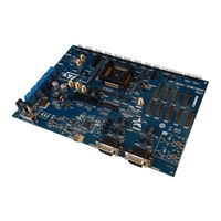
SR5E1-EVBE7000P
ST SR5E1-EVBE7000P Manuals
Manuals and User Guides for ST SR5E1-EVBE7000P. We have
1
ST SR5E1-EVBE7000P manual available for free PDF download: User Manual
ST SR5E1-EVBE7000P User Manual (67 pages)
Brand:
ST
| Category:
Motherboard
| Size: 5 MB
Table of Contents
1 Overview
2
Figure 2. SR5E1-EVBE7000P Rev. C - Top Overview
2
Supported Devices
3
Figure 3. SR5E1-EVBE7000P Rev. C - Bottom Overview
3
2 License Agreement
4
3 Handling Precautions
5
4 Hardware Description
6
Hardware Features
6
Hardware Dimensions
6
5 Power and System Configuration
7
Power Supplies
7
Power Supply Connectors
7
Power Switch, Status Leds and Fuse
7
Table 1. Power Configuration Jumpers
7
Figure 4. 2.1 MM Power Connector
7
System Clock Configuration
9
Figure 5. 40 Mhz Local Crystal Oscillator Schema
9
Figure 6. External Clock Schema
9
Reset Circuit
10
Table 2. System Clock Configuration
10
Figure 7. Reset Circuit Schema
10
TESTMODE Configuration
11
Table 3. Reset Configuration Jumpers
11
Table 4. TESTMODE Configuration Schema
11
Figure 1. SR5E1-EVBE7000P Rev. C
11
Figure 8. TESTMODE Configuration Schema
11
6 Hardware Description
12
CAN Interface
12
Table 5. DSPI Connectors
12
Table 6. CAN_0 DB9 Connector Pinout
12
Table 7. CAN_1 DB9 Connector Pinout
12
Table 8. 8 X 1 Header CAN Connector Pinout
13
Table 9. CAN Configuration Jumpers and Solder Bridges
14
UART Interface
15
Table 10. UART Interface Connectors
15
Table 11. UART Interface Pin Configuration
15
Table 12. UART Interface Leds
16
Figure 9. UART 3 Schema
16
Table 13. UART3 1 X 2 Header Connector (P23) Pinout
17
I²C Interface
18
Table 14. I²C Connector and Jumpers
18
Table 15. I²C Header 1X4 Pins Connector Pinout
18
Figure 10. I²C Schema
18
DSPI Interface
19
Table 16. DSPI Connectors
19
Table 17. DSP_1 Connector (P17) Pin Mapping
19
Figure 11. DSPI Header Connectors Schema
19
Analog and Timers Connectors
20
Table 18. DSP_2 Connector (P19) Pin Mapping
20
Table 19. DSP_4 Connector (P20) Pin Mapping
20
Table 20. Analog and Timers Connectors
20
SAR1_IO ADC Module
21
SAR2_IO ADC Module
21
SAR3_IO ADC Module
21
Table 21. SAR1_IO Connector Pin Mapping (P5)
21
Table 22. SAR2_IO Connector (P7) Pin Mapping
21
Table 23. SAR3_IO Connector (P9) Pin Mapping
21
SADC_IO Module
22
SAR4_IO ADC Module
22
SAR5_IO ADC Module
22
SAR_CAL ADC Module
22
Table 24. SAR4_IO Connector (P10) Pin Mapping
22
Table 25. SAR5_IO Connector (P12) Pin Mapping
22
Table 26. SAR_CAL ADC Connector Pin Mapping
22
Table 27. SADC_IO Connector (P14) Pin Mapping
22
DAC_OUT Module
23
Table 28. DAC_OUT Connector (P16) Pin Mapping
23
Table 29. TIM1 Connector (P6) Pin Mapping
23
Table 30. TIM2_3 Connector (P8) Pin Mapping
23
TIM1 Module
23
TIM2_3 Module
23
Table 31. TIM8 Connector (P11) Pin Mapping
24
Table 32. TIM15 Connector (P13) Pin Mapping
24
Table 33. TIM16 (P15) Connector Pin Mapping
24
TIM15 Module
24
TIM16 Module
24
TIM8 Module
24
HRTIM1 Module
25
HRTIM2 Module
25
Table 34. HRTIM1 Connector (P18) Pin Mapping
25
Table 35. HRTIM2 Connector (P21) Pin Mapping
25
Probe Connectors
26
I/O User Connectors
26
Table 36. Probe Connectors
26
Table 37. I/O User Connectors
26
Debug Connectors
27
Table 38. Debug Connectors
27
Figure 12. JTAG/SWD Debug Ports Schema
27
Table 39. SWJ1 Main DAP Header 2X5 Pins Connector Pinout
28
Table 40. P2 JTAG Header 2X10 Pins Connector Pinout
28
Table 41. JTAG/SWD Configuration
29
Figure 13. Nexus Schema
30
Table 42. Nexus 2X19 Pins Connector Pinout
31
User AREA
32
Figure 14. Nexus 2X19 Pins Connector Pinout
32
Test Points
33
Table 43. Test Points
33
7 Layout Overview
35
Figure 15. SR5E1-EVBE7000P Rev. C - Top Layer
35
Figure 16. SR5E1-EVBE7000P Rev. C - Bottom Layer
36
8 Bom
37
Table 44. Bill of Material
37
9 Schematics
51
Figure 17. Main
51
Figure 18. Power Supply
52
Uc PSU
53
Figure 20. Uc GPIO
54
Figure 21. Program and Debug
55
Figure 22. Analog and Timers
56
Figure 23. HR Timers and Communication
57
Figure 24. CAN-FD
58
Figure 25. USB to UART
59
Figure 26. I/O User 1
60
Figure 27. Analog Validation
61
Revision History
62
Table 45. Document Revision History
62
Advertisement
Advertisement
Related Products
ST STEVAL-IFS012V1
ST STEVAL-IHP007V1
ST STM32L1 Series
ST STM8L15LPBOARD
ST SPC58XXADPT144S REV.B
ST SPC58XXADPT176S
ST STEVAL-IDB007V2
ST STEVAL-IDB009V1
ST SPC5-UDEDEBG
ST STEVAL-IDB008V1M
ST Categories
Motherboard
Computer Hardware
Microcontrollers
Control Unit
Controller
More ST Manuals
Login
Sign In
OR
Sign in with Facebook
Sign in with Google
Upload manual
Upload from disk
Upload from URL