Sign In
Upload
Manuals
Brands
ST Manuals
Control Unit
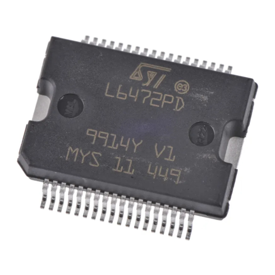
L6472
ST L6472 Manuals
Manuals and User Guides for ST L6472. We have
1
ST L6472 manual available for free PDF download: Manual
ST L6472 Manual (70 pages)
Fully integrated microstepping motor driver
Brand:
ST
| Category:
Control Unit
| Size: 1 MB
Table of Contents
Table 1. Device Summary
1
Table of Contents
2
Block Diagram
8
Figure 1. Block Diagram
8
Electrical Data
9
Absolute Maximum Ratings
9
Recommended Operating Conditions
9
Table 2. Absolute Maximum Ratings
9
Table 3. Recommended Operating Conditions
9
Thermal Data
10
Table 4. Thermal Data
10
Electrical Characteristics
11
Table 5. Electrical Characteristics
11
Pin Connection
16
Figure 2. HTSSOP28 Pin Connection (Top View)
16
Figure 3. POWERSO36 Pin Connection (Top View)
16
Pin List
17
Table 6. Pin Description
17
Typical Applications
19
Table 7. Typical Application Values
19
Figure 4. Bipolar Stepper Motor Control Application Using the L6472
19
Functional Description
20
Device Power-Up
20
Logic I/O
20
Charge Pump
20
Microstepping
21
Figure 5. Charge Pump Circuitry
21
Automatic Full-Step Mode
22
Figure 6. Normal Mode and Microstepping (16 Microsteps)
22
Figure 7. Automatic Full-Step Switching
22
Absolute Position Counter
23
Programmable Speed Profiles
23
Motor Control Commands
23
Constant Speed Commands
24
Positioning Commands
24
Figure 8. Constant Speed Command Examples
24
Motion Commands
25
Stop Commands
25
Figure 9. Positioning Command Examples
25
Figure 10. Motion Command Examples
25
Step-Clock Mode
26
Gountil and Releasesw Commands
26
Internal Oscillator and Oscillator Driver
27
Internal Oscillator
27
External Clock Source
27
Table 8. CL Values According to External Oscillator Frequency
27
Overcurrent Detection
28
Figure 11. OSCIN and OSCOUT Pin Configurations
28
Undervoltage Lockout (UVLO)
29
Thermal Warning and Thermal Shutdown
29
Reset and Standby
29
External Switch (SW Pin)
30
Programmable DMOS Slew Rate, Deadtime and Blanking Time
30
Figure 12. External Switch Connection
30
Integrated Analog-To-Digital Converter
31
Internal Voltage Regulator
31
Figure 13. Internal 3 V Linear Regulator
31
BUSY\SYNC Pin
32
BUSY Operation Mode
32
SYNC Operation Mode
32
FLAG Pin
32
Phase Current Control
33
Predictive Current Control
33
Figure 14. Predictive Current Control
33
Auto-Adjusted Decay Mode
34
Figure 15. Non-Predictive Current Control
34
Figure 16. Adaptive Decay - Fast Decay Tuning
35
Auto-Adjusted Fast Decay During the Falling Steps
36
Figure 17. Adaptive Decay Switch from Normal to Slow + Fast Decay Mode and Vice-Versa
36
Torque Regulation (Output Current Amplitude Regulation)
37
Figure 18. Fast Decay Tuning During the Falling Steps
37
Serial Interface
38
Figure 19. SPI Timings Diagram
38
Figure 20. Daisy Chain Configuration
39
Programming Manual
40
Register and Flag Description
40
Table 9. Register Map
40
Abs_Pos
41
El_Pos
41
Table 10. EL_POS Register
41
Acc
42
Dec
42
Mark
42
Speed
42
Maxspeed 2
43
Minspeed 2
43
Table 11. MIN_SPEED Register
43
Fs_Spd
44
TVAL_HOLD, TVAL_RUN, TVAL_ACC and TVAL_DEC
44
Table 13. T_FAST Register
45
Table 14. Maximum Fast Decay Times
45
Table 15. Minimum on Time
45
Ton_Min
45
T_Fast
45
Adc_Out
46
Table 16. Minimum off Time
46
Table 17. ADC_OUT Value and Torque Regulation Feature
46
Toff_Min
46
Ocd_Th
47
Step_Mode
47
Table 18. Overcurrent Detection Threshold
47
Table 19. STEP_MODE Register
47
Table 20. Step Mode Selection
47
Table 21. SYNC Output Frequency
48
Table 22. SYNC Signal Source
48
Alarm_En
49
Config
49
Table 23. ALARM_EN Register
49
Table 24. CONFIG Register
49
Table 25. Oscillator Management
50
Table 26. External Switch Hard Stop Interrupt Mode
50
Table 27. Overcurrent Event
51
Table 28. Programmable Power Bridge Output Slew Rate Values
51
Table 29. External Torque Regulation Enable
51
Table 30. Switching Period
51
Status
52
Table 31. STATUS Register
52
Table 32. STATUS Register dir Bit
52
Table 33. STATUS Register MOT_STATUS Bits
53
Application Commands
54
Table 34. Application Commands
54
Command Management
55
Figure 21. Command with 3-Byte Argument
55
Figure 22. Command with 3-Byte Response
55
Figure 23. Command Response Aborted
55
Getparam (PARAM)
56
Nop
56
Setparam (PARAM, VALUE)
56
Table 35. NOP Command Structure
56
Table 36. Setparam Command Structure
56
Table 37. Getparam Command Structure
56
Run (DIR, SPD)
57
Stepclock (DIR)
57
Table 38. Run Command Structure
57
Table 39. Stepclock Command Structure
57
Goto (ABS_POS)
58
Move (DIR, N_STEP)
58
Table 40. Move Command Structure
58
Table 41. Goto Command Structure
58
Goto_Dir (DIR, ABS_POS)
59
Gountil (ACT, DIR, SPD)
59
Table 42. Goto_Dir Command Structure
59
Table 43. Gountil Command Structure
59
Gohome
60
Releasesw (ACT, DIR)
60
Table 44. Releasesw Command Structure
60
Table 45. Gohome Command Structure
60
Gomark
61
Resetdevice
61
Resetpos
61
Table 46. Gomark Command Structure
61
Table 47. Resetpos Command Structure
61
Table 48. Resetdevice Command Structure
61
Hardstop
62
Softhiz
62
Softstop
62
Table 49. Softstop Command Structure
62
Table 50. Hardstop Command Structure
62
Table 51. Softhiz Command Structure
62
Getstatus
63
Hardhiz
63
Table 52. Hardhiz Command Structure
63
Table 53. Getstatus Command Structure
63
Package Information
64
HTSSOP28 Package Information
65
Figure 24. HTSSOP28 Package Outline
65
Table 54. HTSSOP28 Package Mechanical Data
66
POWERSO36 Package Information
67
Figure 25. POWERSO36 Package Outline
67
Table 55. POWERSO36 Package Mechanical Data
68
Revision History
69
Table 56. Document Revision History
69
Advertisement
Advertisement
Related Products
ST L6472PD
ST L6472HTR
ST L6472H
ST L6472PDTR
ST L6470H
ST L6470HTR
ST L6470PD
ST L6482H
ST L6482HTR
ST L6387E
ST Categories
Motherboard
Computer Hardware
Microcontrollers
Control Unit
Controller
More ST Manuals
Login
Sign In
OR
Sign in with Facebook
Sign in with Google
Upload manual
Upload from disk
Upload from URL