Sign In
Upload
Manuals
Brands
SPX FLOW Manuals
Water Pump
Johnson Pump TopGear GP120-100
SPX FLOW Johnson Pump TopGear GP120-100 Manuals
Manuals and User Guides for SPX FLOW Johnson Pump TopGear GP120-100. We have
2
SPX FLOW Johnson Pump TopGear GP120-100 manuals available for free PDF download: Instruction Manual
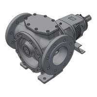
SPX FLOW Johnson Pump TopGear GP120-100 Instruction Manual (124 pages)
Internal Gear Pumps
Brand:
SPX FLOW
| Category:
Water Pump
| Size: 13 MB
Table of Contents
Table of Contents
3
1 Introduction
7
General
7
Reception, Handling and Storage
7
Reception
7
Handling
7
Storage
7
Safety
8
General
8
Pump Units
9
Pump Unit Handling
9
Installation
9
Before Commissioning the Pump Unit
10
Disassembly/Assembly of the Coupling Guard
10
Name Plate - Declaration of Conformity
10
Technical Conventions
11
2 Pump Description
12
Type Designation
12
3 General Technical Information
16
Pump Standard Parts
16
Operating Principle
16
Self-Priming Operation
17
Safety Relief Valve - Working Principle
17
Sound
17
General Performance
17
Main Characteristics
18
Pressure
19
Sound Level
19
Sound Level of a Pump Without Drive
19
The Sound Level of the Pump Unit
20
Influences
20
Material Options
20
Jacket Options
21
Electrical Heating
21
Internals
22
Bush Materials
22
Maximum Temperature of Internals
22
Operation under Hydrodynamic Lubrication Conditions
23
Maximum Torque of Pump Shaft and Rotor Material Combination
23
Mass Moment of Inertia
23
Axial and Radial Clearances
23
Extra Clearances
24
Play between Gear Teeth
25
Maximum Size of Solid Particles
25
Shaft Sealings
25
Packed Gland
25
Packing Ring Materials
25
Mechanical Seals
26
Mechanical Seals According to EN12756 (DIN24960) - General Information
26
Cartridge Mechanical Seals
27
Reverted Packing Execution for E.g. Chocolate Application
28
Triple PTFE Lip-Seal Cartridge
29
Safety Relief Valve
30
Pressure
31
Heating
31
Safety Relief Valve - Relative Adjustment
32
Sectional Drawings and Part Lists
33
Single Safety Relief Valve
33
Heated Spring Casing
34
Double Safety Relief Valve
34
Installation
35
General
35
Location
35
Short Suction Line
35
Accessibility
35
Outdoor Installation
35
Indoor Installation
36
Drives
36
Stability
36
Starting Torque
36
Radial Load on Shaft End
37
Shaft Rotation for Pump Without Safety Relief Valve
37
Shaft Rotation for Pump with Safety Relief Valve
38
Suction and Discharge Pipes
39
Forces and Moments
39
Piping
39
Isolating Valves
40
Strainer
40
Secondary Piping
40
Drain Lines
40
Heating Jackets
41
Flush/Quench Media
42
Packing
42
Single Mechanical Seal
43
Double Mechanical Seal - Tandem Arrangement
43
Cartridge Mechanical Seal
44
Double Mechanical Seal - Back-To-Back Arrangement
44
Secondary Connections
45
Guidelines for Assembly
48
Transport of Pump Unit
48
Foundation Pump Unit
48
Variators, Gear Box, Gear Motors, Motors
48
Electric Motor Drive
48
Combustion Engines
49
Shaft Coupling
49
Guarding of Moving Parts
50
Electrical Heating
50
Instructions for Start-Up
51
General
51
Cleaning the Pump
51
Cleaning Suction Line
51
Venting and Filling
51
Checklist - Initial Start-Up
52
Start-Up
53
Shut-Down
53
Abnormal Operation
53
Trouble Shooting
54
Instructions for Re-Using and Disposal
56
Re-Use
56
Disposal
56
Maintenance Instructions
57
General
57
Preparation
57
Surroundings (on Site)
57
Tools
57
Shut-Down
57
Motor Safety
57
Conservation
57
External Cleaning
58
Electrical Installation
58
Draining of Fluid
58
Fluid Circuits
59
Electrical Heating
59
Specific Components
59
Nuts and Bolts
59
Plastic or Rubber Components
59
Flat Gaskets
59
Filter or Suction Strainer
59
Anti-Friction Bearings
60
Sleeve Bearings
61
Shaft Seals
62
Front Pull-Out
64
Back Pull-Out
64
Clearance Adjustment
64
Designation of Threaded Connections
65
Threaded Connection Rp (Example Rp 1/2)
65
Threaded Connection G (Example G 1/2)
65
4 Instructions for Assembly and Disassembly
66
General
66
Tools
66
Preparation
66
After Disassembly
66
Anti-Friction Bearings
67
General
67
TG GM2-25 and TG GM3-32 Disassembly
67
TG GM2-25 and TG GM3-32 Assembly
67
TG GM6-40 to TG GM360-150 Disassembly
68
TG GM6-40 to TG GM360-150 Assembly
68
Relief Valve
69
Disassembly
69
Assembly
69
Electrical Heating
70
General
70
Electrical Heating on the Pump Cover (in the Idler Pin)
70
Disassembly
70
Assembly
70
Electrical Heating Around Shaft Seal (in the Intermediate Casing)
71
Disassembly
71
Assembly
71
Mechanical Seal
72
General
72
Preparation
72
Special Tools
72
General Instructions During Assembly
73
Assembly of the Stationary Seat
73
Assembly of the Rotating Part
73
Adjustment of Mechanical Seal
74
GS - Single Mechanical Seal
74
GG - Double Mechanical Seal Tandem
78
GD - Double Mechanical Seal "Back-To-Back
78
GC - Mechanical Seal Cartridge
80
Coupling Guard
83
5 Sectional Drawings and Part Lists
86
TG GM2-25 and TG GM3-32
86
Hydraulic Part
87
Bearing Bracket
87
Flange Connection Options
87
S-Jacket Options
88
S-Jacket on Pump Cover
88
S-Jacket Around Shaft Seal
88
Seal Options
88
Packing Rings - PQ
88
Single Mechanical Seal - GS
89
Double Mechanical Seal Tandem - GG
89
Double Mechanical Seal Back-To-Back - GD
89
TG GM6-40 to TG GM360-150
90
Hydraulic Part
91
Bearing Bracket
91
Flange Connection Options
92
Jacket Options and Electrical Heating
93
S-Jacket on Pump Cover
93
S-Jacket Around Shaft Seal
93
T-Jackets with Flange Connections on Pump Cover
94
T-Jackets with Flange Connections Around Shaft Seal
95
Electrical Heating on the Pump Cover (in the Idler Pin)
96
Electrical Heating Around Shaft Seal (in the Intermediate Casing)
97
Shaft Seal Options
98
Packing Rings PQ with Lantern Ring
98
Packing Rings PO Without Lantern Ring
98
Single Mechanical Seal - GS
98
Cartridge Mechanical Seal - GC
99
Double Mechanical Seal Tandem - GG
99
Double Mechanical Seal Back-To-Back - GD
99
Cartridge Triple Lip-Seal - LCT TV (LCT XX)
100
Reverted Packing - Chocolate Version
101
6 Dimensional Drawings
102
Standard Pump
102
TG GM2-25 to TG GM6-40
102
TG GM15-50 to TG GM360-150
103
Flange Connections
104
TG GM2-25 to TG GM6-40
104
TG GM15-50 to TG GM360-150
104
Jackets - Electrical Heating
105
TG GM2-25 to TG GM6-40
105
TG GM15-50 to TG GM360-150
106
Electrical Heating
107
Safety Relief Valves
108
Single Safety Relief Valve
108
Double Safety Relief Valve
108
Heated Safety Relief Valve (S-Jacket)
109
Heated Safety Relief Valve (T-Jacket)
110
Heated Double Safety Relief Valve (S-Jacket)
111
Heated Double Safety Relief Valve (T-Jacket)
112
Bracket Support
113
Weights - Mass
113
Advertisement
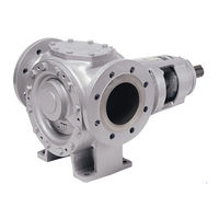
SPX FLOW Johnson Pump TopGear GP120-100 Instruction Manual (92 pages)
Internal Gear Pumps
Brand:
SPX FLOW
| Category:
Water Pump
| Size: 10 MB
Table of Contents
Table of Contents
3
1 Introduction
7
General
7
Reception, Handling and Storage
7
Reception
7
Handling
7
Storage
7
Safety
8
General
8
Pump Units
9
Pump Unit Handling
9
Installation
9
Before Commissioning the Pump Unit
10
Disassembly/Assembly of the Coupling Guard
10
Name Plate - Declaration of Conformity
10
Technical Conventions
11
2 Pump Description
12
Type Designation
12
3 General Technical Information
15
Pump Standard Parts
15
Operating Principle
15
Self-Priming Operation
16
Safety Relief Valve - Working Principle
16
Sound
16
General Performance
16
Main Characteristics
17
Pressure
18
Sound Level
18
Sound Level of a Pump Without Drive
18
The Sound Level of the Pump Unit
19
Influences
19
Material Options
20
Jacket Options
20
Electrical Heating
20
Internals
20
Bush Materials
20
Maximum Temperature of Internals
21
Operation under Hydrodynamic Lubrication Conditions
21
Maximum Torque of Pump Shaft and Rotor Material Combination
22
Mass Moment of Inertia
22
Axial and Radial Clearances
22
Extra Clearances
22
Play between Gear Teeth
23
Maximum Size of Solid Particles
23
Shaft Sealing
24
Packed Gland (no Lantern Ring)
24
Packing Ring Materials
24
Safety Relief Valve
25
Pressure
26
Heating
26
Safety Relief Valve - Relative Adjustment
26
Sectional Drawings and Part Lists
28
Single Safety Relief Valve
28
Heated Spring Casing
29
Double Safety Relief Valve
29
Installation
30
General
30
Location
30
Short Suction Line
30
Accessibility
30
Outdoor Installation
30
Indoor Installation
31
Drives
31
Stability
31
Starting Torque
31
Shaft Rotation for Pump Without Safety Relief Valve
32
Shaft Rotation for Pump with Safety Relief Valve
33
Suction and Discharge Pipes
34
Forces and Moments
34
Piping
34
Isolating Valves
35
Secondary Piping
35
Drain Lines
35
Guidelines for Assembly
37
Transport of Pump Unit
37
Foundation Pump Unit
37
Variators, Gear Box, Gear Motors, Motors
37
Electric Motor Drive
37
Combustion Engines
38
Shaft Coupling
38
Guarding of Moving Parts
39
Electrical Heating
39
Instructions for Start-Up
40
General
40
Cleaning the Pump
40
Venting and Filling
40
Cleaning Suction Line
40
Checklist - Initial Start-Up
41
Start-Up
42
Shut-Down
42
Abnormal Operation
42
Trouble Shooting
43
Instructions for Re-Using and Disposal
45
Re-Use
45
Disposal
45
Maintenance Instructions
46
General
46
Preparation
46
Surroundings (on Site)
46
Tools
46
Shut-Down
46
Motor Safety
46
Conservation
46
External Cleaning
47
Electrical Installation
47
Draining of Fluid
47
Fluid Circuits
47
Electrical Heating
47
Specific Components
48
Nuts and Bolts
48
Plastic or Rubber Components
48
Flat Gaskets
48
Filter or Suction Strainer
48
Anti-Friction Bearings
48
Recommended Greases (also Consult Supplier !)
48
Sleeve Bearings
49
Shaft Seal
50
Front Pull-Out
51
Back Pull-Out
51
Clearance Adjustment
51
Designation of Threaded Connections
52
Threaded Connection Rp (Example Rp 1/2)
52
Threaded Connection G (Example G 1/2)
52
4 Instructions for Assembly and Disassembly
53
General
53
Tools
53
Preparation
53
After Disassembly
53
Anti-Friction Bearings
54
General
54
TG GP2-25, TG GP3-32 and TG GP6-40 Disassembly
54
TG GP2-25, TG GP3-32 and TG GP6-40 Assembly
54
TG GP15-50 to TG GP360-150 Disassembly
55
TG GP15-50 to TG GP360-150 Assembly
55
Relief Valve
56
Disassembly
56
Assembly
56
Electrical Heating
57
General
57
Electrical Heating on the Pump Cover (in the Idler Pin)
57
Disassembly
57
Assembly
57
Electrical Heating Around Shaft Seal (in the Intermediate Casing)
58
Disassembly
58
Assembly
58
Coupling Guard
59
5 Sectional Drawings and Part Lists
62
TG GP2-25 to TG GP6-40
62
Hydraulic Part
63
Bearing Bracket
63
Flange Connection Options
63
Jacket Options
64
Jacket Option on Pump Cover
64
Jacket Option Around Shaft Seal
64
Seal Option: Packing Rings PO
65
TG GP15-50 to TG GP360-150
66
Hydraulic Part
67
Bearing Bracket
67
Jacket Options and Electrical Heating
68
Jacket on Pump Cover
68
Jacket Around the Shaft Seal
68
Electrical Heating on the Pump Cover (in the Idler Pin)
69
Electrical Heating Around Shaft Seal (in the Intermediate Casing)
70
Seal Options: Packing Rings PO
71
6 Dimensional Drawings
72
Standard Pump
72
TG GP2-25 to TG GP6-40
72
TG GP15-50 to TG GP360-150
73
Flange Connections
74
TG GP2-25 to TG GP6-40
74
TG GP15-50 to TG GP360-150
74
Jackets - Electrical Heating
75
Jackets TG GP2-25 to TG GP6-40
75
Jackets TG GP15-50 to TG GP360-150
76
Electrical Heating
77
Safety Relief Valves
78
Single Safety Relief Valve
78
Double Safety Relief Valve
78
Heated Single Safety Relief Valve (S-Jacket)
79
Heated Double Safety Relief Valve (S-Jacket)
80
Bracket Support
81
Weights - Mass
81
Advertisement
Related Products
SPX FLOW Johnson Pump TopGear GP Series
SPX FLOW Johnson Pump TopGear GP185-125
SPX FLOW Johnson Pump TopGear GP360-150
SPX Flow Johnson pump
SPX FLOW Johnson Pump AQUA VOID AUTO RETAIL
SPX FLOW Johnson Pump AQUA VOID AUTO BULK PACKED
SPX Flow Johnson Pump AquaH
SPX Flow Johnson Pump AquaT Silent Electric Compact
SPX Flow Johnson Pump AquaT Silent Electric Comfort
SPX Flow 006-U3
SPX FLOW Categories
Water Pump
Control Unit
Dehumidifier
Power Tool
Water Filtration Systems
More SPX FLOW Manuals
Login
Sign In
OR
Sign in with Facebook
Sign in with Google
Upload manual
Upload from disk
Upload from URL