Sign In
Upload
Manuals
Brands
SPX Manuals
Controller
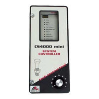
CS4000 Mini
SPX CS4000 Mini Manuals
Manuals and User Guides for SPX CS4000 Mini. We have
1
SPX CS4000 Mini manual available for free PDF download: Technical Reference Manual
SPX CS4000 Mini Technical Reference Manual (106 pages)
Mini Controller with Ethernet
Brand:
SPX
| Category:
Controller
| Size: 1 MB
Table of Contents
Technical Support
2
Limited Warranty
4
Preface
6
Who Should Use this Manual
6
How to Use this Manual
6
Abbreviations
8
Table of Contents
10
1 Overview
16
Receiving, Sending and Storing Data
16
Using Ethernet
17
Example of a "Permanent" (Embedded) Ethernet Network
18
Figure 1-1. Example of an Ethernet Network with a Connected Portable Laptop
18
Using a 485 Network Using SDLC
19
Example of a "Permanent" (Embedded) 485 Network
20
(Using CS4000 KDM and Mini Controllers with SDLC)
20
Figure 1-2. Example of a 485 Network
20
Using the RS-232 Serial Port
21
Using an Interbus-S Digital I/O Module
21
Using the Siemens 3964R Barcode Protocol
22
Deciding How to Set up the Controller
22
2 Think Safety First
24
General Machine Safety
25
Electrical Safety
26
3 Identifying the Components
28
Front Panel
29
LED Display
29
Figure 3-1. Front Panel View
29
Parameter Set Switch
30
Access Screws
30
Top and Bottom Panel
30
AC Power Cord
30
Interbus-S I/O Connector
30
Figure 3-2. Top Panel View
30
I/O Connector
31
Tool Connector
31
Figure 3-3. Bottom Panel View
31
RS-422 Connector
32
Ethernet Connector
32
Printer/Barcode Connector
32
SDLC I/O Network Connector
32
RS-232 Connector
32
Ground Fault Circuit Interrupter
32
Fuses
33
Enclosure Interior
33
Figure 3-4. Components Inside the Enclosure of the CS4000 Mini Controller with Ethernet
34
Figure 3-5. Front View of the TCM
35
Tool Control Module
35
Figure 3-6. Rear View of the TCM and Location of the Servo Amplifier Fuse
36
Device Control Module
37
Figure 3-7. DCM Board and DCM Battery Location
37
Servo Amplifier
37
Backplane
38
Figure 3-8. CS4000 Mini Controller with Ethernet Backplane
38
Address Switches
39
Backplane Fuses
39
Figure 3-9. I/O Board
40
I/O Board
40
Power Supply
40
Ethernet Interface Card
41
Figure 3-10. Ethernet Interface Card
41
Table 3-1. Description of Ethernet Interface Card Leds
42
Figure 3-11. Interbus-S Module Side View
43
Interbus-S Module
43
Figure 3-12. Interbus-S Module Top View
44
Table 3-2. Description of Leds on the Side of the Interbus-S Module
44
Table 3-3. Description of Leds on the Top of the Interbus-S Module
44
Figure 3-13. Ground Fault Circuit Interrupter
45
Fuses
45
Ground Fault Circuit Interrupter
45
4 Installing the CS4000 Mini Controller with Ethernet
46
Mounting the CS4000 Mini Controller with Ethernet
46
Figure 4-1. CS4000 Mini Controller with Ethernet Dimensions
47
Power and Connection-Requirements
48
Figure 4-2. Power/Connection Requirements
48
Meeting the AC Input Power Requirements
49
Grounding
49
I/O Wiring
50
Table 4-1. 19-Position Remote I/O Connector Pinout Signal Names and Descriptions
50
Figure 4-3. Remote Input Circuit Schematics
53
Table 4-2. Guidelines for Proper Operation of the Controller I/O Signals
53
Figure 4-4. Example of CS4000 Controller Remote I/O Wiring Sourcing Outputs
54
Figure 4-5. Example of CS4000 Controller Remote I/O Wiring Sinking Outputs
55
Connector Pinout Definitions
56
Tool Connector
56
I/O Connector
56
RS-422 Connector
57
Tool Control Module (TCM) Network Connector
57
RS-232 Connector
57
Printer/Barcode Connector
57
Interbus-S "IN" Connector
57
Interbus-S "OUT" Connector
58
5 Setting up the Ethernet
60
Programming the Ethernet Interface Card
60
Working with the IP Address, Subnet Mask and Default Gateways
60
Procedure 5-1. Programming the Ethernet Interface Card
61
Figure 5-1. Message Upon Starting the TINI Ethernet Interface Flash Utility
62
Figure 5-2. Selecting the COM Port Menu
63
Figure 5-3. Selecting 'COM1' RS-232 Port
63
Figure 5-4. Establishing a Successful Connection Via COM1
64
Figure 5-5. Error Message Displayed When COM1 Is Already in Use
64
Figure 5-6. Selecting the "Flash TINI..." Option
65
Figure 5-7. Selecting the Application File
65
Figure 5-10. Second Error Message Following an Unsuccessful Flash Attempt
66
Figure 5-8. Error Message Displayed When the Attempted Connection Fails
66
Figure 5-9. Error Message Following an Unsuccessful Flash Attempt
66
Figure 5-11. Confirming the IP Address, Subnet Mask and Default Gateway
67
Figure 5-12. Selecting the "Set TINI Application Info
69
Updating Application Settings
69
Procedure 5-2. Editing Application Information
69
Figure 5-13. Viewing the Application Settings Window - General Info Tab
70
Figure 5-14. Selecting the Application Settings Window - Ip Address Tab
70
Figure 5-15. Selecting the Application Settings Window - Comm Options Tab
71
Setting up Visual Supervisor for an Ethernet Network
72
Editing Vsmain.ini for an Ethernet Network
73
Figure 5-16. Vsmain.ini Configured for an Ethernet Network
73
Procedure 5-3. Editing Vsmain.ini for an Ethernet Network
74
Using Ethernet Network Cables
75
Table 5-1. Ethernet RJ-45 Modular Jack Pinout
75
Procedure 5-4. Testing the Network from a Laptop Computer
76
Testing the Ethernet Network
76
Figure 5-17. Select the Icon and Enter a Name for the Hyperterminal Connection
77
Figure 5-18. Select Communications Port
78
Figure 5-19. Setting the Communications Port Settings
79
Figure 5-20. Hyperterminal Window Showing Ethernet Interface Card (TINI) Login Prompt
80
Figure 5-21. Opening the Command Prompt Window
82
Procedure 5-5. Testing the Network from a Host Computer
82
Testing Ethernet Network Cables
83
6 Setting up the 485 Network
84
Installing the SDLC Card
84
Setting up Visual Supervisor for a 485 Network
84
Editing Vsmain.ini for a 485 Network
85
Figure 6-1. Vsmain.ini Configured for a 485 Network
85
Procedure 6-1. Editing Vsmain.ini for a 485 Network
86
Assigning a Network Address
87
Table 6-1. Switch Positions Representing Binary Numbers
87
Table 6-2. Setting Address Switches
87
Figure 6-2. Network Address DIP Switch Set for Address '5
88
Procedure 6-2. Setting the Address for the Controller
89
Using 485 Network Cables
90
7 Setting up the RS-232 Link
92
Setting up Visual Supervisor
92
Using RS-232 Cables
92
8 Maintenance/Troubleshooting
94
Replacement Parts
94
Table 8-1. Replacement Parts
94
Replacing Main Power Fuses
95
Replacing Backplane Fuses
95
Cleaning the Enclosure Window
95
Troubleshooting
96
Ethernet Network
96
Table 8-2. Ethernet Common Problems and Solutions
96
RS-422 (Siemens 3964R) Interface
97
Application Program Interface (API)
97
9 Technical Information
98
Assembly Drawing
98
Figure 9-1. CS4000 Mini Controller with Ethernet Wiring of Standard Ethernet and Interbus-S Module
100
Figure 9-2. CS4000 Mini Controller with Ethernet Wiring of Standard Ethernet
102
Index
104
Advertisement
Advertisement
Related Products
SPX MARLEY CLASS 800
SPX CM10P7-1
SPX CM30P7-1
SPX POWER TEAM C12-TON
SPX C.A.T4
SPX CUES flexitrax C550c
SPX CUES flexitrax
SPX CUES flexiprobe
SPX CUES flexiprobe C540c
SPX Johnson Pump F3B-1907 Oil Change12 V
SPX Categories
Water Pump
Tools
Control Unit
Industrial Equipment
Security Sensors
More SPX Manuals
Login
Sign In
OR
Sign in with Facebook
Sign in with Google
Upload manual
Upload from disk
Upload from URL