Sign In
Upload
Manuals
Brands
Spectra Engineering Manuals
Accessories
MX800
Spectra Engineering MX800 Repeater Manuals
Manuals and User Guides for Spectra Engineering MX800 Repeater. We have
1
Spectra Engineering MX800 Repeater manual available for free PDF download: Technical Manual
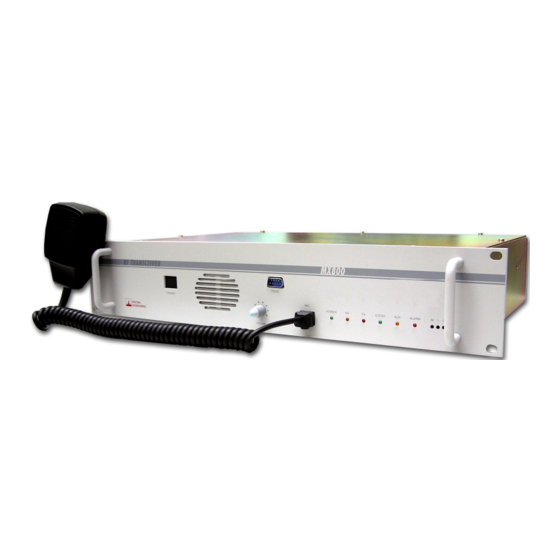
Spectra Engineering MX800 Technical Manual (201 pages)
base station, repeater and transmitter
Brand:
Spectra Engineering
| Category:
Accessories
| Size: 5 MB
Table of Contents
Safety Summary
6
Table of Contents
7
1 General Description
13
Physical Description
15
Front Panel
15
Table 1-1 LED Functions
15
Figure 1-1 Standard Front Panel
16
Figure 1-2 Local Control Front Panel
16
Rear Panel
18
Table 1-2 Rear Panel Connections
18
Figure 1-3 MX800 Rear Panel
18
Side Panel
19
Module Functional Description
19
Exciter Module
19
Figure 1-4 MX800 Side Panel
19
Receiver Module
20
Power Amplifier Module
20
Micro Controller Board
21
2 Installation and Operation
23
Installation
23
Operation
23
MXTOOLS Utility
24
Setting to Work
25
Table 2-1 Micro Controller Jumpers
27
Table 2-2 DIP Switch 2 Settings
28
Adjustments
30
Table 2-3 Power Control Function Settings
30
3 Options
31
T01 Programmable Channel Spacing
31
Description
31
Installation
31
Figure 3-1 MX800 T01 Option, Programable Bandwidth Fitted to RX Module
31
T02 Programmable CTCSS Encoder/Decoder
32
Description
32
Installation
32
T03 Programmable DCS/CTCSS Encoder/Decoder
33
Description
33
Installation
33
Figure 3-2MX800 DCS Option T03
33
T04 Balanced and Isolated VF
34
Description
34
Installation
35
Table 3-1 CN9 Connections
35
Figure 3-3 CN9 RJ45 Pin-Out Detail (View from Rear of MX800)
35
T05 Balanced and Isolated VF Plus E&M
37
Description
37
Table 3-2 CN9 Connections
37
Figure 3-4 MX800 Option T05 Balanced & Isolated VF I/O with E&M Leads
37
Installation
38
Figure 3-5 CN9 RJ45 Pin-Out Detail (View from Rear of MX800)
38
T06 Simplex Changeover Relay
39
Description
39
Figure 3-6 T06 Simplex Changeover Relay
39
Installation
40
T07 Turn Around Mixer
41
T08 VF Delay
42
Description
42
Figure 3-7MX800 T08,T09,T10 Option Board Complete
42
Installation
43
Table 3-3 Option PCB Link Settings
43
T09 300Hz Upgrade HPF Filter
44
Description
44
Installation
45
Table 3-4 Option PCB Link Settings
45
T10 Power Save Mode
46
Description
46
Table 3-5 Current Consumption Details
47
Table 3-6 Option PCB Link Settings
47
Installation
48
T11 Combined Options
49
T12 External Reference Oscillator Input
49
Description
49
Installation
50
T13 Local Speaker, MIC Socket and Front Panel Mute
52
Description
52
Figure 3-8 Front Panel with Speaker, MIC and Mute
52
Installation
53
Table 3-7 MX800 MIC Socket Pinout
53
Figure 3-9 RJ45 Socket Viewed from Front of MX800
53
T14 Local Channel Change
56
Description
56
Installation
56
T16 1PPM Frequency Stability
58
U69 Extended Temperature Range Verification
58
T19/26 Line Interface Board
59
Figure 3-10 MX800 T19/T26Option Board
60
Installation
61
2Wire or 4Wire Selection, Balanced VF
63
VF Delay
63
Table 3-8 Signal Decision Levels/Points and Coresponding Tones
64
Variable & Stepped Tone Encoder
64
Variable Tone Setup Procedure
66
Status Tone Encoding and Decoding (T19 Only)
67
DTMF Decoder
69
Fast CTCSS Decoder
69
Five Tone Encoded / Decoder
69
Remote Control Capabilities
69
Figure 3-11 CN3 Pin-Out Detail (View from Rear of MX800)
70
T19/26 Pinouts
70
Table 3-9 CN3 Connections
70
Figure 3-12 CN9 RJ45 Pin-Out Detail (View from Rear of MX800)
71
Table 3-10 CN9 Connections
71
T19/T26 Jumper Settings
72
Table 3-11 T19/26 Factory Default Jumper Setting
72
T29 Balanced and Isolated VF Plus E&M
73
Figure 3-13 MX800 T29 Otpion Board
73
Table 3-12 T29 RJ45 Pin Outs
74
Table 3-13 T29 Factory Default Jumper Setting
74
Figure 3-14 CN9 RJ45 Pin-Out Detail (View from Rear of MX800)
74
T31 Network Adapter
75
Figure 3-15 T31 Option Board
75
Figure 3-16 U72 Dongle
76
Figure 3-17 U73 Dongle
76
Optional Dongles
76
U72 Dongle
76
U73 Dongle with Digital IO Port Replicator
76
T34 Ethernet Option
77
4 Technical Description
78
Exciter Module
78
Figure 4-1 MX800 Top View
78
Receiver Module
79
Power Amplifier Module
81
Micro Controller Board
81
Overall Radio Management
82
Table 4-1 Microprocessor Port Parameters
82
TX Signal Processing
83
RX Signal Processing
84
RF Power Control
84
User Interface
85
5 Alignment and Testing
86
Transceiver Setup, Calibration and Alignment
86
Sending Model Number and Serial Number to the Radio
86
Sending Configuration Information
87
Sending Channel Information
87
Setting Alignment Channel
87
Power Calibration
88
RSSI Calibration
88
Temperature Calibration
88
TX Power Adjustment
88
Peak Deviation and Modulation Balance
89
Table 5-1 Peak Deviation Settings
89
Figure 5-1 under (Increase Level)
90
Figure 5-2 over (Decrease Level)
90
Figure 5-3 Correctly Aligned Waveform
90
TX Centre Frequency Alignment
91
TX Line Input Level and Nominal Deviation
91
Alignment
91
Table 5-2 Nominal Deviation
91
RX Line Output Level Adjustment
94
TX VF Loop Back Level
94
Mute Threshold Setting
94
Module Level Test Procedures
95
Exciter Module
95
Receiver Module
96
Power Amplifier Module
98
VCO Board
99
Microcontroller Module
100
6 MX800 Base Station Fault Finding Procedure
102
MX800 Base Station
102
Transmitter Section
102
Receiver Section
103
Microcontroller PCB
104
Receiver Module
104
VCO Locking
104
RX Front End
104
IF Section
105
Exciter Module
105
VCO Locking
105
RF Power
105
Power Amplifier
106
7 Appendices
108
MX800 Interface Connections
108
Table 7-1 MX800 Interface Connectors
108
CN1 DB15 Female Line I/O Connector
109
Table 7-2 CN1 Connections
110
CN2 DB9 Female Monitor Connector
111
Table 7-3 CN2 Connections
111
CN3 DB25 Female Digital I/O Connector
112
Table 7-4 CN3 Connections
112
CN4 DB9 Male RS232 Connector
114
CN6 Simplex Relay/External Reference
114
CN7 RX Input
114
CN8 TX Output
114
Cn9 Rj45
114
Table 7-5 CN4 Connector Jumpers
114
CN5 DC Power Input
115
Figure 7-1 CN5 DC Input (View from Rear of MX800)
115
Table 7-6 CN5 DC Power Input Connections
115
MX800 Specifications
116
Operating Frequency Bands
116
General
117
Table 7-7 General Specifications
117
Transmit
118
Table 7-8 Transmit Specifications
118
Receive
119
Table 7-9 Receive Specifications
119
Ancillaries
120
Channel Select DIP Switch Settings
120
Table 7-10 Ancilary Specifications
120
MX800 Model Number Configuration Guide
124
MX800 System Applications
125
Conventional Base Station/Repeater
125
Link Transceiver
125
Figure 7-2MX800 Setup in System Rack
125
Data Transceiver
126
Paging Transmitter
126
Trunking Base Station
127
Systems Base
127
Repeater with Morse ID
127
Simplex Base Station
127
Duplicated Base Station
128
Power Save Base Station
128
Tone Key Base Station
128
Voting Base Station
128
Simulcast Base Station
128
8 Superseded Technical Information
138
Power Amplifier Module
138
Technical Description
138
PA Module Test Procedure
139
PA Fault Finding Procedure
140
9 Drawings
142
Superseded Drawings
143
Table 9-1 Drawings
143
Figure 9-1 Receiver Component Overlay
144
Figure 9-2 Exciter Component Overlay
145
Figure 9-5 Micro Controller Component Overlay (Rev P4)
147
Figure 9-6 Tx and Rx VCO Component Overlay Bands a to Q3
148
Figure 9-7 Tx and Rx VCO Component Overlay Bands R to X
149
Figure 9-8 HP Rx VCO Component Overlay Bands a to Q
150
Advertisement
Advertisement
Related Products
Spectra Engineering RELM BK Radio MX800 T19
Spectra Engineering RELM BK Radio MX800 T26
Spectra Engineering MX940
Spectra Engineering MX940N5V
Spectra Engineering MX950 Series
Spectra Engineering MX950N5H
Spectra Engineering Categories
Computer Hardware
Repeater
Switch
Accessories
More Spectra Engineering Manuals
Login
Sign In
OR
Sign in with Facebook
Sign in with Google
Upload manual
Upload from disk
Upload from URL