Sign In
Upload
Manuals
Brands
Spears Manuals
Control Unit
TRUE UNION 2000 Series
Spears TRUE UNION 2000 Series Manuals
Manuals and User Guides for Spears TRUE UNION 2000 Series. We have
1
Spears TRUE UNION 2000 Series manual available for free PDF download: Manual
Spears TRUE UNION 2000 Series Manual (148 pages)
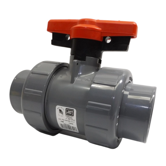
INDUSTRIAL BALL VALVES
Brand:
Spears
| Category:
Control Unit
| Size: 7 MB
Table of Contents
Table of Contents
58
Figure 4.25 - Change Analog out Current - APT 58
61
1 Important Notes
63
Figure 1.1 - QX-05 Actuator
63
2 Quick Start
65
Calibrate - Position Limits
65
Entering the Setup Mode
66
Electrical Operation Feature
66
Figure 2.1 - Electrical Operation
66
Handwheel Operation Feature
67
DDC Option
68
Check the Settings
68
Figure 2.2 - Handwheel Operation
68
3 Installation and Operation
69
Preparing the Stem Nut
69
Torque Applications
69
Table 1.1 - Available QX Flanges
69
Figure 3.1 - Exploded View of QX Bases
70
Mechanical Installation Onto Valve or Gearbox
71
Setting the Mechanical Stops on Quarter-Turn Valves
71
Electrical Connections
72
Removing Terminal Cover
72
Terminal Compartment Documents
72
Figure 3.2 - QX Travel Stops
72
Sealing Cable/Conduit Entries
73
Recommended Terminal Connections
73
Figure 3.3 - Power Terminal Connector Size Limitations
73
Figure 3.4 - Terminal Block Rating; Power Terminals
74
Figure 3.5 - Control Terminal Connector Size Limitations
74
Table 3.1 - Terminal Block Rating; Power Terminals
74
Termination of Cables
75
Cable Connections
75
Figure 3.6 - Control Terminal Connector Size Limitations
75
Table 3.2 - Terminal Block Rating; Control Terminals
75
Network Installations
76
Figure 3.7 - View of Terminal Block
76
Table 3.3 - Required Ratings for External Wires
76
Figure 3.8 - Standard Wiring Diagram
77
Figure 3.9 - Removing Outer Plastic Jacket
77
Figure 3.10 - Separating Cable Parts
78
Figure 3.11 - Stripping Conductors and Applying Heat Shrink Tubing
78
Figure 3.12 - Ring Tongue Connectors
78
Foundation Fieldbus Installation
79
Table 3.4- Loop Topology Connections
79
Network Wiring - Profibus DP/PA Installation
80
Table 3.5 - Foundation Fieldbus Connections
80
Table 3.6 - Profibus Cable Specifications
80
Network Wiring - Devicenet
81
Replacing Terminal Cover
81
External Earth/Ground Connections
81
Terminal Block Shield Installation
81
Table 3.7 - Devicenet Cable Specifications
81
Commissioning the Actuator
82
Default Configuration Set
82
Figure 3.13 - Terminal Block Shield
82
Figure 3.14 - User Network Connection for Loop Topology
83
Figure 3.15 - External Earth/Ground Connection - Housing
83
Table 3.8 - Default Configurations
83
View the Existing Settings
84
Entering the Setup Mode
84
Setting Position Limits
85
Figure 3.16 - View Settings
85
Figure 3.17 - Position Setup - Electrical Operation
87
Operating the QX Actuator
88
Manual Operation
88
Electrical Operation
88
Local Control
88
Figure 3.18 - Declutch Lever Shows Direction of Engagement (QX-05 Shown)
88
Remote Control
89
Local Indication
89
Figure 3.19 - Control Panel
89
Table 3.9 - LED Indicators - Default Settings
89
4 Customizing the Actuator
90
Changing the Existing Settings
90
Figure 4.1 - Entering the Setup Mode
91
Figure 4.2 - Main Menu Selections
92
Figure 4.3 - Changing Settings
92
Password Entry
93
New Password
93
Figure 4.4 - Password Entry
93
Valve Setup
94
Close Direction
94
Close Seating
94
Open Seating
94
Figure 4.5 - New Password
94
Operating Time
95
Torque Setup
95
Close Torque Valve or Open Torque Valve
95
Figure 4.6 - Valve Setup
95
Figure 4.7 - Operating Time Setup
96
Figure 4.8 - Typical XP Nameplate
96
Figure 4.9 - Torque Setup
96
Position Setup
97
Set Position Limits for Electrical Operation
97
Set Position Limits for Manual Operation
97
Figure 4.10 - Electrical Operation
98
Figure 4.11 - Handwheel Operation
98
Modutronic Option
99
Status
99
Proportional Band
99
Fail Position
99
Deadband
99
Polarity (20 Ma)
99
Delay after Stop
99
Ma Signal Range
100
Set High Reference
100
Set Low Reference
100
Figure 4.12 - Modutronic Option
100
Modutronic LCD Display
101
DDC Option
101
Status
101
Figure 4.13 - Modutronic Signals
101
Network Address
102
Protocol
102
Analog Scale
102
ESD Action
102
Proportional Band
102
Figure 4.14 - DDC
102
Deadband
103
Offset
103
Move to
103
Comm Loss Delay
103
Comm Loss Action
103
FF Option
103
Status
104
Terminate Bus
104
Analog Scale
104
ESD Action
104
OPEN/CLOSE Mode
104
Proportional Band
104
Deadband
104
PB Option
105
Figure 4.15 - FF
105
Figure 4.16 - Profibus DP
105
PB DP Operation
106
Status
106
DN Option
107
Status
107
Baud Rate
107
Figure 4.17 - Profibus PA
107
Network Address
108
Analog Scale
108
ESD Action
108
Proportional Band
108
Deadband
108
Figure 4.18 - DN Option
108
Status and Alarm Contacts
109
Status and Alarm Contact Default Settings
109
Status Function
110
Contact
110
Valve Position
110
Figure 4.19 - Status and Alarm Contacts (Shown with Optional Boards Added)
110
Two-Speed Timer (Optional)
111
Status 55
111
Start Position
111
Stop Position
111
Pulse Time - on
111
Pulse Time - off
112
Change Analog out
112
Figure 4.20 - Two-Speed Timers
112
Figure 4.21 - Change Analog out
112
Figure 4.22 - Change Analog out Voltage - APT
113
Figure 4.23 - Change Analog out Current - APT
113
Figure 4.24 - Change Analog out Voltage - ATT
113
APT Polarity Option
114
ATT Polarity Option
115
Remote Mode
115
Figure 4.26 - Remote Control
115
Local Control
116
LED Customization
116
ESD (Emergency Shutdown) Overrides
116
ESD Override
116
Figure 4.27 - Local Control
116
Inhibit
117
Local Command
117
Stop
117
Figure 4.28 - ESD Overrides
117
Jammed Valve
118
Lost Phase
118
Overtorque
118
Motor Thermostat
118
Two-Speed Timer
118
Network ESD
119
Inputs
119
Input Standard Remote Control
119
Status
120
Custom Input Mode - Momentary ESD/PSESD (Optional)
120
Figure 4.29 - Inputs
120
Figure 4.30 - Custom Input Mode
122
Monitor Relay
123
Table 4.1 - Digital Input Terminals
123
Diagnostic Reset
124
Figure 4.31 - Monitor Relay
124
TAG Number
125
Figure 4.32 - Diagnostic Reset
125
LCD Contrast
126
Torque Boost
126
Figure 4.33 - TAG Number
126
Figure 4.34 - LCD Contrast
126
Figure 4.35 - Torque Boost
126
Motor Thermostat
127
Change Valve Data
127
Figure 4.36 - Motor Thermostat
127
Change Port
128
Figure 4.37 - Change Valve Data
128
Figure 4.38 - Change Port and Bluetooth Settings
128
5 Troubleshooting
129
View Diagnostics Routine
129
Troubleshooting Problems/Corrective Action
129
Actuator Fails to Operate
130
Jammed Valve Detected
130
Actuator Operates but Does Not Drive Valve
131
Valve Does Not Seat Correctly
131
Status Messages
131
View Diagnostics
133
Figure 5.1 - Initialize Routine
133
View Hardware Status
134
View Motor Status
134
Figure 5.2 - Diagnostic Overview
134
Figure 5.3 - View Hardware Status
134
View Power Supply
135
View Identification
135
Figure 5.4 - View Motor Status
135
Figure 5.5 - View Power Supply
135
Figure 5.6 - View Identification
135
View Torque Profile
136
View Operation Log
136
Figure 5.7 - View Torque Profile
136
View DNET Status
137
Figure 5.8 - View Operation Log
137
Figure 5.9 - View DNET Status
137
6 Maintenance
139
Lubrication
139
Oil Capacities
139
Checking Oil Level
139
7 Regulatory Information
140
Specific Conditions for Safe Use - Atex/Cenelec/Iecex Applications
143
Statement of Compliance with Applicable European Directives
143
Figure 7.1 - Typical ATEX Nameplate
144
Advertisement
Advertisement
Related Products
Spears Categories
Control Unit
Rivet Tools
More Spears Manuals
Login
Sign In
OR
Sign in with Facebook
Sign in with Google
Upload manual
Upload from disk
Upload from URL