Sign In
Upload
Manuals
Brands
Sorensen Manuals
Power Supply
DLM32-95E
Sorensen DLM32-95E Manuals
Manuals and User Guides for Sorensen DLM32-95E. We have
2
Sorensen DLM32-95E manuals available for free PDF download: Operation Manual
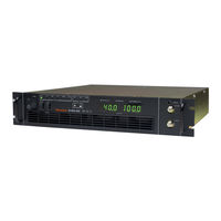
Sorensen DLM32-95E Operation Manual (74 pages)
3kW & 4kW
Brand:
Sorensen
| Category:
Power Supply
| Size: 1 MB
Table of Contents
About AMETEK
5
Important Safety Instructions
7
Warranty Terms
9
About this Manual
11
Table of Contents
13
Section 1 Features and Specifications
19
Description
19
Operating Modes
19
Power Supply Features
19
Specifications
21
Kw DLM-E Electrical Specifications
21
Kw DLM-E Electrical Specifications
22
Additional Specifications
23
Mechanical Specifications
24
Section 2 Installation
25
Introduction
25
Safety
25
High Energy/High Voltage Warning
25
AC Source Grounding
26
EMI Provisions
26
Operating and Servicing Precautions
26
Figure 2-1. EMI Suppression Filter
26
Parts and Modifications
27
Initial Inspection
27
Physical Check
27
Controls, Connectors, and Indicators
27
Front Panel User Controls and Indicators
28
Figure 2-2. DLM-E Controls, Connectors, and Indicators (5V-80V Models)
29
Figure 2-3. DLM-E Controls, Connectors, and Indicators (150V-600V Models)
30
Rear Panel
31
Location, Mounting, and Ventilation
32
Unit Dimensions
32
Rack Mounting
32
Ventilation
32
AC Input Power Connection
33
AC Input Power Requirements
33
Input Line Impedance
33
Initial Functional Tests
34
Load Connection
34
Load Conductor Ratings
35
Noise and Impedance Effects
35
Making the Connections
36
Connecting Single Loads
36
Figure 2-4. Single Load with Local Sensing (Default)
36
Connecting Multiple Loads
37
Figure 2-5. Single Load with Remote Sensing
37
Figure 2-6. Multiple Loads with Local Sensing
38
Figure 2-7. Multiple Loads with Remote Sensing
38
Section 3 Basic Operation
39
Introduction
39
Standard Operation
39
Operating Modes and Automatic Crossover
39
Figure 3-1. Operating Modes
40
Local Programming Mode Operation
41
Figure 3-2. Local Mode Default Configuration
41
Using Remote Sensing
42
Connecting Remote Sense Lines
42
Figure 3-3. J11 Sense Connector
43
Section 4 Advanced Operation
45
Introduction
45
Configuring for Remote Programming, Sensing, and Monitoring
46
Programming, Monitoring, and Control Functions
46
Rear Panel DIP Switch
47
Table 4-1. J3 Connector - Program, Control, and Monitor Description
47
Figure 4-1. J3 Connector
47
Resetting Rear Panel DIP Switch Settings
48
Making J3 Connections
48
Table 4-2. Rear Panel S1 DIP Switch Functions and Settings
48
Figure 4-2. Locating Jumpers, Switch, and Connector
48
Remote Programming of Output Voltage and Current Limit
49
Programming Output Voltage and Current Limit with the REMOTE/LOCAL Switch
50
Programming Output Voltage
52
Figure 4-4. Programming Output Voltage with a 0-5 VDC or 0-10 VDC Source
52
Figure 4-5. Programming Output Voltage with a 0-5K Ohm Resistance
53
Programming Output Current Limit
54
Figure 4-6. Programming Output Current Limit with a 0-5 VDC or 0-10 VDC Source
54
Figure 4-7. Programming Output Current Limit with a 0-5K Ohm Resistance
55
Remote Programming Only the Output Voltage or Current Limit
56
Using over Voltage Protection (OVP)
58
Front Panel OVP Operation
58
Resetting the OVP Circuit
58
Programming OVP with an External Voltage Source
59
Figure 4-10. Remote Programming of OVP with a 0-5 VDC or 0-10 VDC External Voltage Source
59
Figure 4-11. Remote Programming of OVP with a 0-5K Ohm Resistance
60
Using the Shutdown Function
61
STANDBY Switch
61
Programming the Shutdown Function
61
Shutdown Application - Contact Closure
62
Figure 4-12. Using Shutdown with a DC Input (Positive Logic)
62
Figure 4-13. Using Shutdown with Contact Closure of a Normally OPEN Relay (S1-6
63
Figure 4-14. Using Shutdown with Contact Closure of a Normally OPEN Relay (S1-6 Down)
63
Figure 4-15. Using Shutdown with Contact Closure of a Normally CLOSED Relay (S1-6 Up)
63
Remote Monitoring
64
Readback Signals
64
Figure 4-16. Using Shutdown with Contact Closure of Normally CLOSED Relay (S1-6 Down)
64
Status Indicators
65
Using Multiple Supplies
65
Configuring Multiple Supplies for Series Operation
65
Configuring Multiple Supplies for Split Supply Operation
66
Figure 4-17. Series Operation of Multiple Supplies
66
Figure 4-18. Split Supply Operation of Multiple Supplies (Two Positive Voltages)
67
Configuring Multiple Supplies for Parallel Operation
68
Table 4-3. J12, J13 Connectors-Parallel Port Function and Pinout
68
Front Panel Lockout
69
Fault Alarm Signal
69
Figure 4-20. Parallel Operation of Multiple Supplies
69
Section 5 Maintenance and Troubleshooting
71
Periodic Service
71
Troubleshooting
71
Preliminary Checks
71
Troubleshooting at the Operation Level
72
Table 5-1. User Diagnostics
72
Calibration
73
Table 5-2. Potentiometer Adjustment Procedures
73
Figure 5-1. Potentiometer Locations
73
Ordering Parts
74
Fuse Ratings
74
Table 5-3. Fuse Ratings
74
Advertisement
Sorensen DLM32-95E Operation Manual (66 pages)
14 W
Brand:
Sorensen
| Category:
Power Supply
| Size: 1 MB
Table of Contents
Power Supplies
1
Safety Notice
5
About this Manual
8
Table of Contents
9
Section 1 Features and Specifications
13
Description
13
Operating Modes
13
Power Supply Features
13
Specifications
15
Kw DLM-E Electrical Specifications
15
Kw DLM-E Electrical Specifications
16
Additional Specifications
17
Mechanical Specifications
18
Section 2 Installation
19
Introduction
19
Safety
19
High Energy/High Voltage Warning
19
AC Source Grounding
20
EMI Provisions
20
Figure 2-1. EMI Suppression Filter
20
Operating and Servicing Precautions
21
Parts and Modifications
21
Initial Inspection
21
Physical Check
21
Controls, Connectors, and Indicators
22
Front Panel User Controls and Indicators
22
Figure 2-2. DLM-E Controls, Connectors, and Indicators (5V-80V Models)
23
Figure 2-3. DLM-E Controls, Connectors, and Indicators (150V-600V Models)
24
Rear Panel
25
Location, Mounting, and Ventilation
26
Unit Dimensions
26
Rack Mounting
26
Ventilation
26
AC Input Power Connection
27
AC Input Power Requirements
27
Input Line Impedance
27
Initial Functional Tests
28
Load Connection
28
Load Conductor Ratings
29
Noise and Impedance Effects
29
Making the Connections
30
Connecting Single Loads
30
Figure 2-4. Single Load with Local Sensing (Default)
30
Connecting Multiple Loads
31
Figure 2-5. Single Load with Remote Sensing
31
Figure 2-6. Multiple Loads with Local Sensing
32
Figure 2-7. Multiple Loads with Remote Sensing
32
Section 3 Basic Operation
33
Introduction
33
Standard Operation
33
Operating Modes and Automatic Crossover
33
Figure 3-1. Operating Modes
34
Local Programming Mode Operation
35
Figure 3-2. Local Mode Default Configuration
35
Using Remote Sensing
36
Connecting Remote Sense Lines
36
Figure 3-3. J11 Sense Connector
37
Section 4 Advanced Operation
39
Introduction
39
Configuring for Remote Programming, Sensing, and Monitoring
40
Programming, Monitoring, and Control Functions
40
Figure 4-1. J3 Connector
40
Rear Panel DIP Switch
41
Table 4-1. J3 Connector - Program, Control, and Monitor Description
41
Figure 4-2. Locating Jumpers, Switch, and Connector
41
Resetting Rear Panel DIP Switch Settings
42
Making J3 Connections
42
Table 4-2. Rear Panel S1 DIP Switch Functions and Settings
42
Remote Programming of Output Voltage and Current Limit
43
Programming Output Voltage and Current Limit with the REMOTE/LOCAL Switch
44
Figure 4-3. Programming Output Voltage, Current Limit and OVP with REM/LOC Switch
44
Programming Output Voltage
45
Figure 4-4. Programming Output Voltage with a 0-5 VDC or 0-10 VDC Source
45
Figure 4-5. Programming Output Voltage with a 0-5K Ohm Resistance
46
Programming Output Current Limit
47
Figure 4-6. Programming Output Current Limit with a 0-5 VDC or 0-10 VDC Source
47
Figure 4-7. Programming Output Current Limit with a 0-5K Ohm Resistance
48
Remote Programming Only the Output Voltage or Current Limit
49
Figure 4-8. Programming Output Voltage Remotely, Local Control of Current Limit/Ovp
49
Figure 4-9. Programming Output Current Remotely, Local Control of Voltage Limit/Ovp
50
Using over Voltage Protection (OVP)
51
Front Panel OVP Operation
51
Resetting the OVP Circuit
51
Programming OVP with an External Voltage Source
52
Figure 4-10. Remote Programming of OVP with a 0-5 VDC or 0-10 VDC External Voltage Source
52
Figure 4-11. Remote Programming of OVP with a 0-5K Ohm Resistance
53
Using the Shutdown Function
54
STANDBY Switch
54
Programming the Shutdown Function
54
Shutdown Application - Contact Closure
55
Figure 4-12. Using Shutdown with a DC Input (Positive Logic)
55
Figure 4-13. Using Shutdown with Contact Closure of a Normally OPEN Relay (S1-6 Up)
56
Figure 4-14. Using Shutdown with Contact Closure of a Normally OPEN Relay (S1-6 Down)
56
Figure 4-15. Using Shutdown with Contact Closure of a Normally CLOSED Relay (S1-6 Up)
56
Remote Monitoring
57
Readback Signals
57
Figure 4-16. Using Shutdown with Contact Closure of Normally CLOSED Relay (S1-6 Down)
57
Status Indicators
58
Using Multiple Supplies
58
Configuring Multiple Supplies for Series Operation
58
Configuring Multiple Supplies for Split Supply Operation
59
Figure 4-17. Series Operation of Multiple Supplies
59
Figure 4-18. Split Supply Operation of Multiple Supplies (Two Positive Voltages)
60
Figure 4-19. Split Supply Operation of Multiple Supplies (Positive-Negative Supply)
60
Configuring Multiple Supplies for Parallel Operation
61
Table 4-3. J12, J13 Connectors-Parallel Port Function and Pinout
61
Front Panel Lockout
62
Figure 4-20. Parallel Operation of Multiple Supplies
62
Section 5 Maintenance and Troubleshooting
63
Periodic Service
63
Troubleshooting
63
Preliminary Checks
63
Troubleshooting at the Operation Level
64
Table 5-1. User Diagnostics
64
Calibration
65
Table 5-2. Potentiometer Adjustment Procedures
65
Figure 5-1. Potentiometer Locations
65
Ordering Parts
66
Fuse Ratings
66
Table 5-3. Fuse Ratings
66
Advertisement
Related Products
Sorensen DLM300-10E
Sorensen DLM32-125E
Sorensen DLM300-13E
Sorensen DLM 300-2
Sorensen DLM5-450E
Sorensen DLM8-450E
Sorensen DLM150-26E
Sorensen DLM600-6.6E
Sorensen DLM 10-60
Sorensen DLM 5-75
Sorensen Categories
Power Supply
Controller
Industrial Electrical
Recording Equipment
More Sorensen Manuals
Login
Sign In
OR
Sign in with Facebook
Sign in with Google
Upload manual
Upload from disk
Upload from URL