Sign In
Upload
Manuals
Brands
Sonifex Manuals
Media Converter
Redbox RB-SD1
Sonifex Redbox RB-SD1 Manuals
Manuals and User Guides for Sonifex Redbox RB-SD1. We have
4
Sonifex Redbox RB-SD1 manuals available for free PDF download: User Handbook Manual, Introduction Manual, Specification
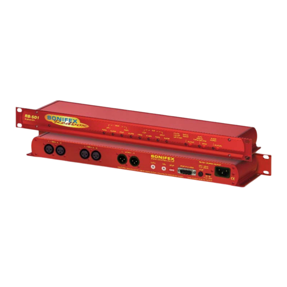
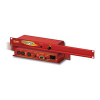
Sonifex Redbox RB-SD1 User Handbook Manual (160 pages)
Digital Audio Converters, Synchronisers, Delays & Silence Detectors
Brand:
Sonifex
| Category:
Media Converter
| Size: 2 MB
Table of Contents
Table of Contents
3
Warranty
10
Figures
10
Warranty and Liability - Important the Purchaser Is Advised to Read this Clause I
10
Unpacking the Redbox
10
Fig A: Packing List
10
Warranty Registration
11
Safety Information
11
Safety of Mains Operated Equipment
11
Voltage Setting Checks
11
Fuse Rating
11
Power Cable and Connection
12
Ordering the Correct Mains Lead
12
Installation Information
12
Fig B: Mains Cable Wire Colours
12
Fig C: Mains Lead Table
12
Fig D: RB-Rk1Small Redbox Front Rack-Mount Kit
13
Fig E: RB-RK2 Small Redbox Rear Rack-Mount Kit
13
Fig F: RB-RK3 Large Redbox Rear Rack-Mount Kit
13
Installing the Optional Video Sync Boards in the RB-DSD1
14
Opening the RB-DSD1
14
Fig G: RB-DSD1 Optional Video Sync Installation
15
WEEE & Rohs Directives - Sonifex Statement
16
RB-ADDA Combined A/D and D/A Converter
17
Introduction
17
Fig 1-1: RB-ADDA Front Panel
17
System Block Diagram
18
Front Panel Indicators
18
Rear Panel Connections and Operation
18
Fig 1-2: RB-ADDA System Block Diagram
18
Fig 1-3: RB-ADDA Rear Panel
18
Fig 1-4: RB-ADDA Full Scale Db Settings
20
Fig 1-5: RB-ADDA Status Select Switches
21
Fig 1-6: RB-ADDA Frequency and Sync Rotary Switch
22
Technical Specifications RB-ADDA
23
RB-ADDA2 Combined A/D and D/A Converter 24Bit 192Khz
24
Introduction
24
Fig 2-1: RB-ADDA2 Front Panel
24
Master Mode
25
Slave Mode
25
Auto Mode
25
Auto Lock Mode
25
System Block Diagram
26
Front Panel Controls & Indicators
26
Fig 2-2: RB-ADDA2 System Block Diagram
26
Fig 2-3: SYNC Button & Leds
26
Fig 2-4: A/D SOURCE Select Button & Leds
26
Fig 2-5: FREQUENCY Set Button & Leds
26
Rear Panel Connections and Operation
27
Fig 2-6: CS DATA Button & Leds
27
Fig 2-7: BITS Button & Leds
27
Fig 2-8: D/A SOURCE Select Button & Leds
27
Fig 2-9: RB-ADDA2 Rear Panel
27
Serial Port Control
30
Serial Interface Commands and Responses
30
Upgrading Firmware
33
Technical Specifications RB-ADDA2
33
RB-SC1 Sample Rate Converter
36
Introduction
36
System Block Diagram
36
Fig 3-1: RB-SC1 Front Panel
36
Fig 3-2: RB-SC1 System Block Diagram
36
Front Panel Indicators
37
Rear Panel Connections and Operation
37
Fig 3-3: RB-SC1 Rear Panel
37
Fig 3-4: RB-SC1 Status Switches
38
Fig 3-5: RB-SC1 Frequency and Sync Rotary Switch Settings
39
Technical Specifications RB-SC1
40
RB-SC2 Dual Sample Rate Converter, 24Bit 192Khz
41
Introduction
41
Fig 4-1: RB-SC2 Front Panel
41
Fig 4-2: RB-SC2 X-Lock Sync Mode
42
Installing the Optional Video Sync Boards
43
Opening the RB-SC2
43
Follow These Instructions to Fit Either of the Sync Boards
44
System Block Diagram
44
Fig 4-3: RB-SC2 Optional Video Sync Installation
44
Fig 4-4: RB-SC2 System Block Diagram
44
Fig 4-5: FREQUENCY Set Button & Leds
45
Front Panel Controls & Indicators
45
Fig 4-6: CS DATA Button & Leds
45
Fig 4-7: INPUT 1 & INPUT2
45
Fig 4-8: SYNC Button & Leds
45
Fig 4-9: RB-SC2 Rear Panel
46
Serial Port Control
47
Technical Specification RB-SC2
50
Upgrading Firmware
50
RB-DAC1 Digital to Analogue Converter
52
Introduction
52
System Block Diagram
52
Fig 5-1: RB-DAC1 Front Panel
52
Fig 5-2: RB-DAC1 System Block Diagram
52
Front Panel Indicators & Controls
53
Sync & Power Indicator
53
Headphone Output
53
Volume Control
53
Rear Panel Connections and Operation
53
Fig 5-3: RB-DAC1 Front Panel
53
Fig 5-4: RB-DAC1 Rear Panel
53
RB-DAC1 Inputs
54
RB-DAC1 Outputs
54
Rear Panel Controls
54
Fig 5-5: RB-DAC1 Full Scale Digits and De-Emphasis Settings Switches
54
Technical Specifications RB-DAC1
55
RB-SP1 Digital Splitter & Combiner
57
Introduction
57
System Block Diagram
57
Fig 6-1: RB-SP1 Front Panel
57
Fig 6-2: RB-SP1 System Block Diagram
57
Front Panel Indicators & Controls
58
Front Panel Led's
58
Type & Mode Switches
58
Fig 6-3: RB-SP1 Front Panel
58
Rear Panel Connections and Operation
60
Fig 6-4: RB-SP1 Type and Mode Flow Diagrams
60
Fig 6-5: RB-SP1 Rear Panel
60
Inputs and Outputs
61
Rear Panel Controls
61
Fig 6-6: RB-SP1 Mode Select Dip Switches
61
Technical Specifications RB-SP1
62
RB-DS2 Audio Delay Synchroniser
64
Introduction
64
Fig 7-1: RB-DS2 Front Panel
64
Extended Mode Using Compact Flash
65
Extended FAT Mode
65
Front Panel Controls
66
Fig 7-2: RB-DS2 System Block Diagram
66
Fig 7-3: Front Panel CONTROL
66
Rear Panel Connections and Operation
67
Fig 7-4: RB-DS2 Rear Panel
67
The Default Screen
69
Fig 7-5: the Default Screen
69
The Main Menu
70
Fig 7-6: the Main Menu
70
Serial Port Control
76
Serial Interface Commands and Responses
76
Upgrading Firmware
80
Technical Specifications RB-DS2
81
Opening the RB-DS2 to Add a Compact Flash Card
82
Fig 7-7: Maximum Delays in Normal Mode (Using On-Board Memory Only)
83
Fig 7-8: Maximum Delays in Extended FAT Mode with 1 GB Compact Flash™ Memory Card Installed
84
Fig 7-9: Maximum Delays in Extended RAW Mode with 16 GB Compact Flash™ Memory Card Installed
85
RB-PD2 Stereo Profanity Delay
87
Introduction
87
Fig 8-1: RB-PD2 Front Panel
87
System Block Diagram
89
Quickstart Guide
89
Fig 8-2: RB-PD2 System Block Diagram
89
Using the Audio Stretch Method of Operation
90
Using the Play File Method of Operation
91
Front Panel Controls
93
Setting the Delay
93
Fig 8-3: RB-PD2 Rotary Control Operation
93
Fig 8-4: RB-PD2 Front Panel Buttons
94
Rear Panel Connections
96
Fig 8-5: RB-PD2 Rear Panel
96
The Default Screen
98
Fig 8-6: the Default Screen
98
The Main Menu
98
Fig 8-7: the Main Menu Screen
98
Fig 8-8: the Record Screen
102
Serial Port Control
107
Serial Interface Commands and Responses
107
Upgrading Firmware
114
Technical Specification RB-PD2
115
RB-SD1 Silence Detection Unit
117
Introduction
117
Fig 9-1: RB-SD1 Front Panel
117
System Block Diagram
118
Rear Panel Connections and Operation
118
Fig 9-2: RB-SD1 System Block Diagram
118
Fig 9-3: RB-SD1 Rear Panel
118
A/B Inputs (Left and Right)
119
Outputs
119
Silence Detect Trigger Level
119
Silence Detect Interval Control
119
Mode Dip Switch Settings
119
Remotes Connector
121
Front Panel Selectors and Indicators
121
Fig 9-4: RB-SD1 Front Panel
121
Source Select and Indicator
122
Mode Selector and Indicator
122
Main and Aux Indicators
122
Alarm Indicator
123
Restore Button
123
Additional Modes
123
D Redbox User Handbook no
124
Technical Specifications RB-SD1
125
10 RB-DSD1 Digital Silence Detection Unit
127
Introduction
127
Fig 10-1: RB-DSD1 Front Panel
127
Master Mode
128
Auto Sync Mode
128
Auto Lock Mode
128
Slave Mode
128
Front Panel Controls and Indicators
129
Fig 10-2: RB-DSD1 System Block Diagram
129
Fig 10-3: RB-DSD1 Front Panel Controls and Indicators
129
MAIN Source Select and Indicators
130
AUX Source Select and Indicators
130
RESTORE Button
130
SYNC Mode Button
130
SERIAL Mode Indicator
130
Reset Button
130
Front Panel Dipswitches
131
Silence Detect Duration Control
131
Serial Mode Setting
131
Silence Detect Audio Trigger Level
131
Fig 10-4: SILENCE Detect Duration Dipswitch
131
Fig 10-5: SILENCE Detect Audio Trigger Level Dipswitch
131
Fig 10-6: SILENCE Detect Stereo/Mono & Sync Source Dipswitch
131
Rear Panel Controls
132
Output Sample Rate Selection
132
Fig 10-7: Rear Panel Dipswitches
132
Remotes Connector
135
Rs232
136
RB-DSD1 Inputs & Outputs
136
AES/EBU Inputs
136
S/PDIF Inputs
136
Optical Inputs
136
AES/EBU Sync Input
136
Fig 10-8: RB-DSD1 Rear Panel
136
Word Clock Input
137
The S/PDIF Digital Phono Input Has an Impedance of 75Ω
137
AES/EBU Outputs
137
S/PDIF Outputs
137
Optical Outputs
137
Serial Interface Commands and Responses
138
Serial Port Control
138
Serial Protocol RB-DSD1
138
Serial Interface Commands and Responses
138
Fig 10-9: Serial Port Default Settings
138
Indication
144
Fig 10-10: Indication
144
Unit Setup
145
Fig 10-11: Unit Setup
145
Select Synchronization Options
146
Select Trigger and Switch Time Options
146
Select Operational Modes
146
Miscellaneous
147
Updating the Firmware
147
Fig 10-12: Miscellaneous
147
Special Modes
148
Technical Specification for RB-DSD1
149
Connectors & Cabling
152
XLR 3 Pin Connectors
152
RCA Phono Connectors
152
Fig 11-1: XLR Connectors
152
Fig 11-2: RCA Phono Connector
152
Fig 11-3: ¼" Jack Connector
152
Fig 11-4: 25 Way D-Type Connectors
153
Fig 11-5: 15 Way D-Type Connectors
153
Fig 11-6: 9 Way D-Type Connectors
153
D-Type Connectors
154
Glossary
154
Advertisement
Sonifex Redbox RB-SD1 User Handbook Manual (136 pages)
Brand:
Sonifex
| Category:
Recording Equipment
| Size: 4 MB
Table of Contents
Table of Contents
3
Product Warranty - 2 Year Extended
8
Sonifex Warranty & Liability Terms & Conditions
8
Definitions
8
Warranty
8
Unpacking Your Product
10
Repairs & Returns
10
Conformity
10
Safety & Installation of Mains Operated Equipment
10
Voltage Setting Checks
10
Fuse Rating
10
Power Cable & Connection
10
WEEE Directive
11
Atmosphere/Environment
11
Fitting Redboxes
11
Fig A: RB-Rk1Small Redbox Front Rack-Mount Kit
11
Fig B: RB-RK2 Small Redbox Rear Rack-Mount Kit
12
Fig C: RB-RK3 Large Redbox Rear Rack-Mount Kit
12
RB-SD1 Silence Detection Unit
13
Introduction
13
Fig 1-1: RB-SD1 Front Panel
13
System Block Diagram
14
Fig 1-2: RB-SD1 System Block Diagram
14
Rear Panel Connections and Operation
15
Fig 1-3: RB-SD1 Rear Panel
15
Front Panel Selectors and Indicators
17
Fig 1-4: RB-SD1 Front Panel
17
Source Select and Indicator
18
Additional Modes
19
Technical Specifications RB-SD1
21
Fig 2-1: RB-SD1IP Front Panel
22
RB-SD1IP Silence Detection Unit with Ethernet & USB
22
Introduction
22
Fig 2-2: RB-SD1IP System Block Diagram
24
System Block Diagram
24
Rear Panel Connections and Operation
25
Fig 2-3: RB-SD1IP Rear Panel
25
Remote Alarms Connector
26
Front Panel Selectors and Indicators
28
Mode DIP Switch Settings
25
Fig 2-4: RB-SD1IP Front Panel
28
RB-SD1IP Network Discovery and Webserver
31
Fig 2-5: Sonifex Service Discovery - Bonjour Page
32
Fig 2-6: Sonifex Service Discovery - Legacy Discovery Page
32
Home Page
33
Sonifex Service Discovery App
32
Fig 2-7: RB-SD1IP Screenshot of the Webserver Home Page
33
Device Information
34
Fig 2-8: RB-SD1IP Screenshot of the Webserver Device Page
34
Network Settings
35
Fig 2-9: RB-SD1IP Screenshot of the Webserver Network Settings Page
35
Configuration : Level & Time Settings
36
Fig 2-10: RB-SD1IP Screenshot of the Webserver Level & Time Settings Page
36
Configuration : Source Settings
37
Fig 2-11: RB-SD1IP Screenshot of the Webserver Sources Page
37
Configuration : Alarm Settings
38
Fig 2-12: RB-SD1IP Screenshot of the Webserver Alarms Page
38
Configuration : SNMP Settings
39
Fig 2-13: RB-SD1IP Screenshot of the Webserver SNMP Page
39
Configuration : USB Settings
40
Fig 2-14: RB-SD1IP Screenshot of the Webserver USB Page
40
Configuration : Remote Settings
41
Fig 2-15: RB-SD1IP Screenshot of the Webserver Remotes
41
Configuration : GPIO Settings
42
Fig 2-16: RB-SD1IP Screenshot of the Webserver GPIO Page
42
Configuration : Physical Settings
43
Fig 2-17: RB-SD1IP Screenshot of the Webserver Physical Settings Page
43
Update
44
Fig 2-18: RB-SD1IP Screenshot of the Webserver Update Firmware Page
44
Technical Specification RB-SD1IP
45
Fig 3-1: RB-DSD1 Front Panel
46
RB-DSD1 Digital Silence Detection Unit
46
Introduction
46
Fig 3-2: RB-DSD1 System Block Diagram
48
Fig 3-3: RB-DSD1 Front Panel Controls and Indicators
48
Front Panel Controls and Indicators
48
Front Panel Dipswitches
49
Fig 3-4: SILENCE Detect Duration Dipswitch
49
Rear Panel Controls
50
Fig 3-5: SILENCE Detect Audio Trigger Level Dipswitch
50
Fig 3-6: SILENCE Detect Stereo/Mono & Sync Source Dipswitch
50
Fig 3-7: Rear Panel Dipswitches
50
Remotes Connector
53
Fig 3-8: RB-DSD1 Rear Panel
54
RB-DSD1 Inputs & Outputs
54
Fig 3-9: Serial Port Default Settings
55
Serial Port Control
55
Sci for RB-DSD1
59
Serial Interface Commands and Responses
55
Serial Protocol RB-DSD1
55
Fig 3-10: Indication Page
59
Unit Setup Page
60
Indication Page
59
Fig 3-11: Unit Setup Page
60
Miscellaneous Page
61
Fig 3-12: Miscellaneous Page
61
Special Modes
62
Technical Specification for RB-DSD1
63
Fig 4-1: RB-DSD8 Front Panel
65
RB-DSD8 8 Channel Silence Switcher
65
Display Leds
67
Fig 4-2: RB-DSD8 Status Buttons
67
Fig 4-3: RB-DSD8 Controls & Indicators for each Channel
67
Status Buttons
67
Fig 4-4: RB-DSD8 Additional Indicators
69
Front Panel Controls & Indicators
67
Rear Panel Dipswitch Settings
70
Fig 4-5: RB-DSD8 Rear Panel Dipswitches
70
RB-DSD8 Rear Panel Connections
73
Audio Connections
73
Fig 4-6: RB-DSD8 Rear Panel
73
Fig 4-7: Audio & GPI/O Connector Detail
73
GPI/O Remotes Connector
74
Fig 4-8: Audio Connector Pin Numbers
74
Fig 4-9: GPI/O Remotes Connector Pin Numbers
74
Alarm Output Pins
75
Control Inputs
75
Slave Socket
76
USB Remote Control
76
Ethernet
76
Wordclock & AES Synchronisation Input
76
Dual IEC Main Inputs
76
Fig 4-10: Communications Connectors
76
Remote Control
77
Serial Interface Commands & Responses
77
Error Messages
80
Slave Control
77
Sci for RB-DSD8
80
Status Page
80
Fig 4-11: Status Page
81
Channel Status Page
82
Fig 4-12: Channel Status Page
82
Miscellaneous Page
83
Fig 4-13: Miscellaneous Page
83
Webserver
84
Fig 4-14: General Settings Page
84
Connecting to the Device
85
Webserver Password
85
Updating the Firmware
86
Technical Specification RB-DSD8
87
Fig 5-1: the RB-FS42 Front Panel
89
RB-FS42 Audio Failover Switcher, 4 Main I/O, 2 Standby I/O
89
Introduction
89
Fig 5-2: the RB-FS42 Diagram
91
Connections & Operation
92
Fig 5-3: the RB-FS42 Front Panel
92
Front Panel
92
Fig 5-4: the RB-FS42 Rear Panel
94
25 Way D-Type Connection Details
95
Fig 5-5: the RB-FS42 Female and Male Connectors
95
Rear Panel Connections
94
Typical Application
97
Network Discovery & Webserver Configuration
98
Fig 5-6: the RB-FS42 Bonjour Panel
101
Device Info
102
Fig 5-8: the RB-FS42 Device Info Panel
102
Home Page
103
Fig 5-9: the RB-FS42 Home Screen
103
Network Settings
104
Fig 5-10: the RB-FS42 Network Settings Screen
104
Snmp
105
Fig 5-11: the RB-FS42 SNMP Screen
105
Channel Settings
106
Fig 5-12: the RB-FS42 Channel Settings Screen
106
Power Supply Trap Settings
107
Fig 5-13: the RB-FS42 Power Supply Trap Settings Screen
107
GPO Settings
108
Fig 5-14: the RB-FS42 GPO Settings Screen
108
LED Settings
109
Fig 5-15: the RB-FS42 LED Settings Screen
109
Update
110
Fig 5-16: the RB-FS42 Update Screen
110
Technical Specifications RB-FS42
111
Fig 6-1: the RB-FS82 Front Panel
113
RB-FS82 Audio Failover Switcher, 8 Main I/O, 2 Standby I/O
113
Introduction
113
Fig 6-2: the RB-FS82 Diagram
115
Connections & Operation
116
Fig 6-3: the RB-FS82 Front Panel
116
Rear Panel Connections
118
Front Panel
116
Fig 6-4: the RB-FS82 Rear Panel
118
25 Way D-Type Connection Details
119
Fig 6-5: the RB-FS82 Female and Male Connectors
119
Typical Application
121
GPI Operation
122
Network Discovery & Webserver Configuration
122
Fig 6-6: the RB-FS82 Bonjour Panel
125
Fig 6-7: the RB-FS82 Legacy Discovery Panel
125
Device Info
126
Fig 6-8: the RB-FS82 Device Info Panel
126
Home Page
127
Fig 6-9: the RB-FS82 Home Screen
127
Network Settings
128
Fig 6-10: the RB-FS82 Network Settings Screen
128
Snmp
129
Fig 6-11: the RB-FS82 SNMP Screen
129
Channel Settings
130
Fig 6-12: the RB-FS82 Channel Settings Screen
130
Power Supply Trap Settings
131
Fig 6-13: the RB-FS82 Power Supply Trap Settings Screen
131
GPO Settings
132
Fig 6-14: the RB-FS82 GPO Settings Screen
132
LED Settings
133
Fig 6-15: the RB-FS82 LED Settings Screen
133
Update
134
Fig 6-16: the RB-FS82 Update Screen
134
Technical Specifications RB-FS82
135
Sonifex Redbox RB-SD1 Introduction Manual (62 pages)
Digital Audio Converters, Synchronisation Add-On Boards, Synchronisers, Delays & Silence Detectors, Matching Converters, Audio Distribution Amplifiers, Tone Generators, Video Embedders & De-Embedders
Brand:
Sonifex
| Category:
Amplifier
| Size: 3 MB
Advertisement
Sonifex Redbox RB-SD1 Specification (2 pages)
Silence Detection Unit
Brand:
Sonifex
| Category:
Recording Equipment
| Size: 0 MB
Advertisement
Related Products
Sonifex Redbox RB-SP1
Sonifex Redbox RB-SC1
Sonifex Redbox RB-SC2
Sonifex Redbox RB-VHEDD8
Sonifex RB-ADDA
Sonifex Redbox RB-DS2
Sonifex Redbox RB-ADDA2
Sonifex RB-PD1
Sonifex Redbox RB-DAC1
Sonifex Redbox RB-DS2R
Sonifex Categories
Recording Equipment
Media Converter
Amplifier
Mixer
Intercom System
More Sonifex Manuals
Login
Sign In
OR
Sign in with Facebook
Sign in with Google
Upload manual
Upload from disk
Upload from URL