Sign In
Upload
Manuals
Brands
Sonifex Manuals
Amplifier
Redbox RB-HD6
Sonifex Redbox RB-HD6 Manuals
Manuals and User Guides for Sonifex Redbox RB-HD6. We have
3
Sonifex Redbox RB-HD6 manuals available for free PDF download: User Handbook Manual, Introduction Manual
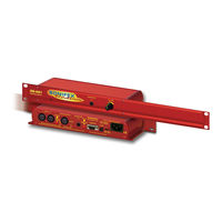
Sonifex Redbox RB-HD6 User Handbook Manual (72 pages)
Matching Converters, Distribution Amplifiers & Headphone Amplifiers
Brand:
Sonifex
| Category:
Amplifier
| Size: 0 MB
Table of Contents
Table of Contents
3
Fig A: Packing List
10
Warranty
10
Unpacking the Redbox
10
Returning the Warranty Card
11
Safety Information
11
Safety of Mains Operated Equipment
11
Voltage Setting Checks
11
Fuse Rating
11
Power Cable and Connection
12
Fig D: RB-Rk1Small Redbox Front Rack-Mount Kit
13
Fig E: RB-RK2 Small Redbox Rear Rack-Mount Kit
13
Fig F: RB-RK3 Large Redbox Rear Rack-Mount Kit
13
Ordering the Correct Mains Lead
12
Installation Information
12
Atmosphere
12
Electromagnetic Radiation
12
Fig B: Mains Cable Wire Colours
12
Fig C: Mains Lead Table
12
Fitting Redboxes
12
WEEE & Rohs Directives - Sonifex Statement
14
Matching Converters
15
1 RB-UL1 Single, RB-UL2 Dual & RB-UL4 Quad Stereo Unbalanced to Balanced Converters
15
Fig 1-1: RB-UL1 & RB-UL2 Front Panel
15
Fig 1-2: RB-UL4 Front Panel
15
Fig 1-3: Block Diagram for a Single Channel
15
Introduction
15
System Block Diagram
15
Fig 1-4: RB-UL1 Rear Panel
16
Fig 1-5: RB-UL2 Rear Panel
16
Fig 1-6: RB-UL4 Rear Panel
16
RCA Phono Inputs (Left and Right)
17
Outputs (Left and Right)
17
Output Level Adjustment
17
Rb-Ul4
18
Technical Specifications
18
Rear Panel Connections and Operation
16
Fig 2-1: RB-LU4 Front Panel
19
2 RB-LU4 Quad Stereo Balanced to Unbalanced Converter
19
Fig 2-2: RB-LU4 Block Diagram
20
Inputs 1-4 (Left and Right)
21
Rear Panel Connections and Operation
21
RCA Phono Outputs 1-4 (Left and Right)
21
Output Level Adjustment
21
System Block Diagram
20
Fig 2-3: RB-LU4 Rear Panel
21
Technical Specifications
22
Introduction
19
11 RB-HD1 Stereo Headphone Amplifier & RB-HD2 Dual
23
Fig 3-1: RB-BL2 Front Panel
23
Fig 3-2: RB-BL4 Front Panel
23
Introduction
23
3 RB-BL2 Single & RB-BL4 Dual Bi-Directional Matching Converter
23
Fig 3-3: RB-BL2/BL4 Block Diagram Single Stereo Channel
24
Fig 3-4: RB-BL2 Rear Panel
24
Rear Panel Connections and Operation
24
System Block Diagram
24
Balanced to Unbalanced Connections
25
Inputs 1 (& 3) (Left & Right)
25
RCA Phono Outputs 1 (&3) (Left & Right)
25
Output Level Adjustment
25
Fig 3-5: RB-BL4 Rear Panel
25
Unbalanced to Balanced Connections
25
RCA Phono Inputs 2 (& 4) (Left & Right)
25
Outputs 2 (& 4) (Left & Right)
25
Technical Specifications
26
Fig 4-1: RB-PA2 Front Panel
27
Fig 4-2: RB-PA2 Block Diagram for a Single Stereo Channel
27
Introduction
27
4 RB-PA2 Dual Stereo RIAA Phono Amplifier
27
System Block Diagram
27
Fig 4-3: RB-PA2 Rear Panel
28
Output Level Adjustment
28
Pick-Up Grounding Post
28
Outputs (Left and Right)
28
RCA Phono Inputs (Left and Right)
28
Rear Panel Connections and Operation
28
Technical Specifications
29
Fig 5-1: RB-LI2 Front Panel
30
Fig 5-2: RB-LI2 System Block Diagram
30
Inputs
31
Introduction
30
5 RB-LI2 Stereo Line Isolation Unit
30
Fig 5-3: RB-LI2 Rear Panel
31
Internal Jumpers
32
Rear Panel Connections and Operation
31
Isolated Outputs
31
Loop Outputs
31
Output Level Adjustment
31
Fig 5-4: RB-LI2 Jumper Positions on the PCB
32
Technical Specifications
32
Fig 6-1: RB-PLI6 Front Panel
33
Fig 6-2: RB-PLI6 System Block Diagram
33
Outputs
34
Rear Panel Connections and Operation
34
Inputs
34
Ground-Link Internal Jumpers
34
Introduction
33
6 RB-PLI6 6 Way Mono Passive Line Isolation Unit
33
Fig 6-3: RB-PLI6 Rear Panel
34
Fig 6-4: RB-PLI6 Ground-Link Jumper Settings
34
Technical Specifications
35
Fig 7-1: RB-DA6 Front Panel
36
Fig 7-2: RB-DA6G Front Panel
36
Introduction
36
7 RB-DA6 & RB-DA6G 6 Way Stereo Distribution Amplifier
36
Fig 7-3: RB-DA6 Block Diagram
37
Fig 7-4: RB-DA6G Block Diagram
37
System Block Diagram
37
Connections and Operation
38
Inputs (Left & Right)
38
Input Gain Control (RB-DA6)
38
Output Gain Control (RB-DA6G)
38
Fig 7-5: RB-DA6 & RB-DA6G Rear Panel
38
Fig 7-6: RB-DA6 Front Panel
38
Stereo/Mono Operation
39
Technical Specifications
39
Fig 7-7: RB-DA6G Front Panel
39
Fig 8-1: RB-Da4X5 Front Panel
40
Audio Inputs 1-4
41
System Block Diagram
41
Introduction
40
8 RB-Da4X5 4 Input, 4 X 5 Output Distribution Amplifier/Mixer
40
Fig 8-2: RB-Da4X5 Block Diagram
41
Fig 8-3: RB-Da4X5 Rear Panel
41
Rear Panel Connections and Operation
41
D-Type Audio Output Groups 1-4
42
Fig 8-4: RB-Da4X5 Audio Output Group15-Way D-Type Plug
42
Fig 8-5: RB-Da4X5 Pinout for Audio Output Group Connector
42
Fig 8-6: RB-Da4X5 Routing Selection Switch
42
Alignment Test Tone
43
Technical Specifications
43
Input Level Adjustment
42
Monitor Leds
42
Output Level Adjustment
42
Routing Selection
42
Fig 8-7: RB-Da4X5 Routing Selection Switch Functions
43
RB-DDA6S 6 Way Stereo S/PDIF Digital Distribution Amplifier
44
Fig 9-1: RB-DDA6A/S Front Panel
44
Introduction
44
Fig 9-2: RB-DDA6A System Block Diagram
45
9 RB-DDA6A 6 Way Stereo AES/EBU Digital Distribution Amplifier and
44
System Block Diagrams
45
Fig 9-3: RB-DDA6S System Block Diagram
46
System Block Diagrams
46
Fig 9-4: RB-DDA6A Rear Panel
47
Fig 9-5: RB-DDA6S Rear Panel
47
Rear Panel Connections and Operations
47
AES/EBU Input
47
AES/EBU Outputs
47
S/PDIF Input
47
S/PDIF Outputs
47
Technical Specifications
48
Fig 10-1: RB-DDA6W Front Panel
49
Introduction
49
10 RB-DDA6W 6 Way Word Clock Distribution Amplifier
49
Fig 10-2: RB-DDA6W System Block Diagram
50
Word Clock Input
51
Fig 10-3: RB-DDA6W Rear Panel
51
Rear Panel Connections and Operations
51
Word Clock Outputs
51
Technical Specifications
51
Fig 11-1: RB-HD1 Front Panel
52
Fig 11-2: RB-HD2 Front Panel
52
Introduction
52
RB-HD1 Stereo Headphone Amplifier & RB-HD2 Dual Headphone Amplifier
52
Fig 11-3: RB-HD1 Block Diagram
53
Fig 11-4: RB-HD2 Block Diagram
53
System Block Diagrams
53
Fig 11-5: RB-HD1 Front Panel Controls
54
Fig 11-6: RB-HD2 Front Panel Controls
54
Main Stereo Inputs (Left and Right)
55
Rear Panel Connections and Operation
55
Stereo Input Gain Adjustment (RB-HD1)
55
Front Panel Connections and Controls
54
Volume Level Control
54
Channel Volume Controls
54
Fig 11-7: RB-HD1 Rear Panel
55
Fig 11-8: RB-HD2 Rear Panel
55
Mono MIX Input (RB-HD1)
56
Stereo/Mono Operation
56
Mono MIX Input Gain Adjustment (RB-HD1)
56
Local/Remote Control Operation (RB-HD1)
56
Fig 11-9: RB-HD1 Remote Connector
56
Technical Specifications
57
Fig 12-1: RB-HD6 Front Panel
58
Introduction
58
12 RB-HD6 6 Way Headphone Distribution Amplifier
58
Fig 12-2: RB-HD6 Block Diagram
59
System Block Diagram
59
Stereo Input (Left and Right)
60
Rear Panel Connections and Operation
60
Stereo/Mono Operation
60
Channel Insertion Inputs/Parallel Outputs
60
Removing the Equipment Covers
60
Fig 12-3: RB-HD6 Rear Panel
60
Configuring Insert Inputs/Parallel Outputs
61
Fig 12-4: RB-HD6 Jumper Assignments
61
Fig 12-5: RB-HD6 Jumper Positions
61
Fig 12-6: RB-HD6 Front Panel Controls
61
Channel Volume Controls
62
Technical Specifications
62
Front Panel Connections and Controls
61
Fig 12-7: RB-HD6 Master Level Control
62
Fig 13-1: RB-DHD6 Front Panel
63
Fig 13-2: RB-DHD6 System Block Diagram
63
Fig 13-3: RB-DHD6 Front Panel Controls
63
Sync & Power Indicator
64
Headphone Outputs
64
Volume Control
64
Rear Panel Connections and Operation
64
AES/EBU Input
64
S/PDIF Input
64
Front Panel Indicators & Controls
63
13 RB-DHD6 Digital 6 Way Headphone Distribution Amplifier
63
Fig 13-4: RB-DHD6 Rear Panel
64
Fig 13-5: RB-DHD6 Status Select Switches
64
Digital Input Select Button
65
Technical Specifications
65
Introduction
63
14 Connectors & Cabling
66
Fig 14-1: XLR Connectors
66
Fig 14-2: RCA Phono Connector
66
Fig 14-3: ¼" Jack Connector
66
RCA Phono Connectors ¼
66
XLR 3 Pin Connectors
66
Fig 14-4: 25 Way D-Type Connectors
67
Fig 14-5: 15 Way D-Type Connectors
67
Fig 14-6: 9 Way D-Type Connectors
67
15 Glossary
68
Advertisement
Sonifex Redbox RB-HD6 User Handbook Manual (68 pages)
Brand:
Sonifex
| Category:
Amplifier
| Size: 1 MB
Table of Contents
Table of Contents
2
Tel: +44 (0)1933 650
5
Fax: +44 (0)1933 650
5
Product Warranty - 2 Year Extended
6
Sonifex Warranty & Liability Terms & Conditions
6
Definitions
6
Warranty
6
Unpacking Your Product
7
Repairs & Returns
8
Conformity
8
Safety & Installation of Mains Operated Equipment
8
Voltage Setting Checks
8
Fuse Rating
8
Power Cable & Connection
8
WEEE Directive
9
Atmosphere/Environment
9
Fitting Redboxes
9
Fig A: RB-RK1 Small Redbox Front Rack-Mount Kit
9
Fig B: RB-RK2 Small Redbox Rear Rack-Mount Kit
10
Fig C: RB-RK3 Large Redbox Rear Rack-Mount Kit
10
1 RB-HD1 Stereo Headphone Amplifier with VCA Volume Control
11
Introduction
11
System Block Diagrams
11
Fig 1-1: RB-HD1 Front Panel
11
Fig 1-2: RB-HD1 System Block Diagram
11
Front Panel Connections and Controls
12
Fig 1-3: RB-HD1 Front Panel Controls
12
Fig 1-4: RB-HD1 Rear Panel
12
Rear Panel Connections and Operation
12
Fig 1-5: RB-HD1 Remote Connector
13
Technical Specifications RB-HD1
14
Redbox Handbook
15
Redbox User Handbook no
15
2 RB-HD2 Dual Headphone Amplifier
15
Introduction
15
System Block Diagrams
15
Fig 2-1: RB-HD2 Front Panel
15
Fig 2-2: RB-HD2 System Block Diagram
15
Front Panel Connections and Controls
16
Fig 2-3: RB-HD2 Front Panel Controls
16
Fig 2-4: RB-HD2 Rear Panel
16
Rear Panel Connections and Operation
16
Technical Specifications RB-HD2
17
3 RB-HD6 6 Way Stereo Headphone Distribution Amplifier
18
Introduction
18
Fig 3-1: RB-HD6 Front Panel
18
System Block Diagram
19
Fig 3-2: RB-HD6 System Block Diagram
19
Rear Panel Connections and Operation
20
Fig 3-3: RB-HD6 Rear Panel
20
Front Panel Connections and Controls
21
Fig 3-5: RB-HD6 Jumper Positions
21
Fig 3-6: RB-HD6 Front Panel Controls
21
Fig 3-7: RB-HD6 Master Level Control
21
Technical Specifications RB-HD6
22
4 RB-DHD6 Digital 6 Way Headphone Distribution Amplifier
23
Introduction
23
System Block Diagram
23
Fig 4-1: RB-DHD6 Front Panel
23
Fig 4-2: RB-DHD6 System Block Diagram
23
Rear Panel Connections and Operation
24
Fig 4-3: RB-DHD6 Front Panel Controls
24
Fig 4-4: RB-DHD6 Rear Panel
24
Front Panel Indicators & Controls
24
Fig 4-5: RB-DHD6 Status Select Switches
25
Technical Specifications RB-DHD6
26
5 RB-MA1 Single Microphone Amplifier
27
Introduction
27
System Block Diagram
27
Fig 5-1: RB-MA1 Front Panel
27
Fig 5-2: RB-MA1 System Block Diagram
27
Rear Panel Connections and Operation
28
Fig 5-3: RB-MA1 Rear Panel
28
Fig 5-4: Switch to Control LF Filter and Phantom Power
28
Technical Specifications RB-MA1
29
6 RB-MA2 Dual Microphone Amplifiers
30
Introduction
30
System Block Diagram
30
Fig 6-1: RB-MA2 Front Panel
30
Rear Panel Connections and Operation
31
Fig 6-3: RB-MA2 Rear Panel
31
Fig 6-4: Switch to Control LF Filter and Phantom Power
31
Technical Specifications RB-MA2
32
7 RB-MA2G Dual Microphone Amplifier with Gain
33
Introduction
33
Fig 7-1: RB-MA2G Front Panel
33
System Block Diagram
34
Rear Panel Connections and Operation
34
Fig 7-2: RB-MA2G System Block Diagram
34
Fig 7-3: RB-MA2G Rear Panel
34
Front Panel Controls
35
Fig 7-4: Switch to Control LF Filter and Phantom Power
35
Technical Specifications RB-MA2G
36
8 RB-DMA2 Dual Digital Microphone Amplifier
37
Introduction
37
Fig 8-1: RB-DMA2 Front Panel
37
System Block Diagram
38
Front Panel Indicators & Controls
38
Fig 8-2: RB-DMA2 System Block Diagram
38
Fig 8-3: RB-DMA2 Front Panel
38
Rear Panel Connections and Operation
39
Fig 8-4: Jumpers to Disable Fine Gain Control
39
Fig 8-5: RB-DMA2 Rear Panel
39
Fig 8-6: RB-DMA2 Status Select Switches
40
Technical Specifications RB-DMA2
42
Stock Code
40
Rear Panel Controls
40
Fig 8-7: RB-DMA2 Frequency and Sync Rotary Switch Selections
42
9 RB-ML2 Stereo Microphone & Line Level Limiter
44
Introduction
44
Fig 9-1: RB-ML2 Front Panel
44
System Block Diagram
45
Rear Panel Connections and Operation
45
Fig 9-2: RB-ML2 System Block Diagram
45
Fig 9-3: RB-ML2 Rear Panel
45
Fig 9-4: Switch to Control LF Filter and Phantom Power
46
Technical Specifications RB-ML2
47
10 RB-SL2 Twin Mono, or Stereo, Limiter
48
Introduction
48
Fig 10-1: RB-SL2 Front Panel
48
System Block Diagram
49
Rear Panel Connections and Operation
49
Fig 10-2: RB-SL2 System Block Diagram
49
Fig 10-3: RB-SL2 Rear Panel
49
Technical Specifications RB-SL2
51
11 RB-SM1 Single Stereo to Mono Converter
52
Introduction
52
System Block Diagram
52
Fig 11-1: RB-SM1 Front Panel
52
Fig 11-2: RB-SM1 System Block Diagram
52
Rear Panel Connections and Operation
53
Fig 11-3: RB-SM1 Rear Panel
53
Technical Specifications RB-SM1
54
12 RB-SM2 Dual Stereo to Mono Converter Introduction
55
System Block Diagram
55
Fig 12-1: RB-SM2 Front Panel
55
Rear Panel Connections and Operation
56
Fig 12-3: RB-SM2 Rear Panel
56
Technical Specifications RB-SM1, RB-SM2
57
13 RB-LC3 3 Way Light/Power Controller
58
Introduction
58
Fig 13-1: RB-LC3 Front Panel
58
System Block Diagram
59
Rear Panel Connections and Operation
59
Fig 13-2: RB-LC3 System Block Diagram
59
Fig 13-3: RB-LC3 Rear Panel
59
Fig 13-4: Output 1 Configuration Setting
61
Fig 13-5: Output 2 Configuration Settings
62
Fig 13-6: Output 3 Configuration Settings
63
Technical Specifications RB-LC3
64
Sonifex Redbox RB-HD6 Introduction Manual (62 pages)
Digital Audio Converters, Synchronisation Add-On Boards, Synchronisers, Delays & Silence Detectors, Matching Converters, Audio Distribution Amplifiers, Tone Generators, Video Embedders & De-Embedders
Brand:
Sonifex
| Category:
Amplifier
| Size: 3 MB
Advertisement
Advertisement
Related Products
Sonifex Redbox RB-HD1
Sonifex Redbox RB-HD2
Sonifex Redbox RB-DA6P
Sonifex Redbox RB-DA6G
Sonifex Redbox RB-DDA6A-2P
Sonifex Redbox RB-VHDA2X4
Sonifex Redbox RB-DA6RG
Sonifex Redbox RB-DDA6A3
Sonifex Redbox RB-MSP6
Sonifex Redbox RB-UL1
Sonifex Categories
Recording Equipment
Media Converter
Amplifier
Mixer
Intercom System
More Sonifex Manuals
Login
Sign In
OR
Sign in with Facebook
Sign in with Google
Upload manual
Upload from disk
Upload from URL