Sign In
Upload
Manuals
Brands
Sonic Manuals
Marine Equipment
2024
Sonic 2024 Manuals
Manuals and User Guides for Sonic 2024. We have
1
Sonic 2024 manual available for free PDF download: Operation Manual
Sonic 2024 Operation Manual (210 pages)
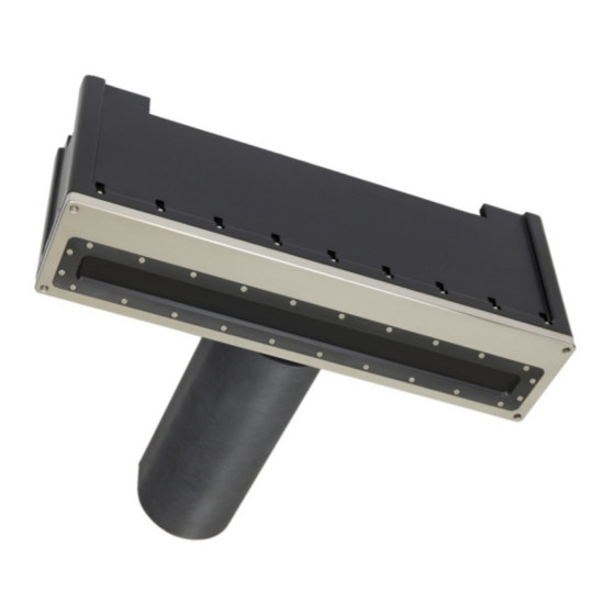
BROADBAND MULTIBEAM ECHOSOUNDERS
Brand:
Sonic
| Category:
Marine Equipment
| Size: 8 MB
Table of Contents
Table of Contents
5
List of Tables
18
1 Introduction
19
Outline of Equipment
19
Figure 1: Sonic 2024/2022 Block Diagram
19
How to Use this Manual
20
Standard of Measurement
20
Table 1: Metric to Imperial Conversion Table
20
2 Sonic Specifications
21
Sonic 2024 System Specification
21
Sonic 2022 System Specification
21
Sonic 2024 Dimensions and Weights
21
Table 2: System Specification
21
Table 3: Component Dimensions and Mass
21
Sonic 2022 Dimensions and Weights
22
Sonic 2024/Sonic 2022 Electrical Interface
22
Sonic 2024/2022 Ping Rates (SV = 1500.00M/Sec)
22
Table 4: Electrical Interface
22
Table 5: Ping Rate Table
22
Acoustic Centre
23
Figure 2: Sonic 2024 Acoustic Centre
23
Figure 3: Sonic 2024 Acoustic Centre as Mounted
23
Figure 4: Sonic 2022 Acoustic Centre
24
Figure 5: Sonic 2022 Acoustic Centre as Mounted
24
3 SONIC 2024/2022 SONAR HEAD INSTALLATION - Surface Vessel
25
Sonic 2024/2022 Receive Module Installation
25
Figure 6: Sonic 2024 and Sonic 2022 on the Mounting Frame
25
Mounting the Sonic 2024/2022 Receive Module
26
Receive Module
26
Figure 7: Top Side of Receive Module
26
Figure 8: Receive Module Face
26
Figure 9: Seated Connectors (Sonic 2024 on Left and Sonic 2022 on Right)
26
Figure 10: Connector Wiggle - Back and Forth NOT up and down
26
Mounting the Projector
27
Figure 11: Receive Module with Cables Connected
27
Figure 12: Sonic 2024 Projector
27
Figure 13: Position the Insulating Bushing, then Wrap Threads with Teflon Tape, then Secure with Flat Washer, Locking Washer and then Nut
27
Figure 14: Projector Stand-Off
28
Figure 15: Mounting the Projector
28
Figure 16: View of the Mounted Projector; NB. Connector Is Facing Protective Fin
28
Figure 17: SV Probe Mounted in Block
28
Correct Orientation of the Sonic 2024 and Sonic 2022
29
Deck Test Prior to Deployment
29
Figure 18: Correct Orientation of the Sonic 2024 and the Sonic 2022
29
Sonar Head Installation Guidelines
31
Introduction
31
Over-The-Side Mount
31
Figure 19: Typical Over-The-Side Mount
31
Moon Pool Mount
32
Hull Mount
32
ROV Mounting
32
4 SONIC 2024/2022 SONAR INTERFACE MODULE (SIM) INSTALLATION and INTERFACING
33
Sonar Interface Module (SIM)
33
Physical Installation
33
Figure 20: Sonar Interface Module (SIM)
33
Electrical and Interfacing
34
Figure 21: Removal of Trim to Expose Securing Holes
34
Figure 22: SIM Interfacing Physical Connections
35
Figure 23: SIM Interfacing Guide (from Label on Top of the SIM)
35
Figure 24: SIM IEC Mains Connection and Deck Lead Amphenol Connector
36
Figure 25: Impulse Connector
36
Table 6: Deck Lead Pin Assignment (Gigabit Ethernet and Power)
36
Figure 26: Projector Cable Configuration
37
Serial Communication
38
Time and PPS Input
38
Figure 27: TTL Input/Output (PPS and Sync In/Out) Schematic
38
Table 7: DB-9M RS-232 Standard Protocol
38
Table 8: SIM DB-9M Serial Pin Assignment
38
Motion Input
39
SVP Input
39
5 Operation of the Sonic 2024/2022 Via Sonic Control
41
Installing Sonic Control Graphical User Interface
41
Hot Keys
41
Figure 28: Sonic Control Icon on Desktop
41
Figure 29: Sonic Control 2000
41
Network Setup
42
Initial Computer Setup for Communication
42
Figure 30: Windows XP Internet Properties
42
Discover Function
43
Figure 31: IP and Subnet Mask Setup
43
Figure 32: Sonic Control Network Setup
44
Figure 33: Set ins IP
44
Figure 34: Set IP Time Expired
44
Configuring Network Communication
45
Figure 35: Command Prompt-Ipconfig/All
45
Sensor Setup (Serial and Ethernet Interfacing)
47
Gps
47
Motion
47
Heading
47
Figure 36: Sensor Communication Settings
47
Svp
48
Message Displays
48
Trigger in / Trigger out
48
Figure 37: Trigger In/Out Options
48
Sonar Settings (Hotkey: F2)
49
Figure 38: Sonar Operation Settings Window
49
Frequency (Khz)
50
Figure 39: Operating Frequency Selection
50
Figure 40: UHR Frequency Available
50
Ping Rate Limit
51
Sector Coverage
51
Figure 41: Ping Rate Limit
51
Sector Rotate
52
Figure 42: Sector Coverage
52
Figure 43: Sector Rotate
52
Minimum Range Gate (M)
53
Bottom Sampling
53
Figure 44: Bottom Sampling Modes
53
Mission Mode
54
Figure 45: Example of Going from Normal to Quad Mode
54
Figure 46: Indication of Bottom Sampling Mode
54
Figure 47: Normal Mission Mode Selections
54
Figure 48: Mission Mode with the FLS Option Installed
54
Imagery
55
Figure 49: Enable Acoustic Image in the Wedge Display
55
Figure 50: FLS Wide Mode
56
Figure 51: Imagery Palette Selection in Display Options
56
Figure 52: Stealth Mode Single Ping Button
56
Roll Stabilize
57
Figure 53: Roll Stabilize
57
Dual Head Mode (also See Appendix VII, Section 13.9)
58
Figure 54: Dual Head Mode
58
Figure 55: Dual Head Mode Active
58
Figure 56: Load Settings Menu Selection
59
Figure 57: Loading an .Ini File
59
Figure 58: Default Dual Head Network Settings
59
Truepix™, Snippets, Water Column Enable and Intensity Enable
60
Figure 59: Truepix™ Image of Wreck Debris and Sea Grass
60
Ocean Setting
61
Absorption: 0 - 200 Db/Km
61
Spreading Loss: 0 - 60 Db
61
Figure 60: Ocean Characteristics
61
Time Variable Gain
62
Figure 61: TVG Curve Concept
62
Figure 62: the Angular Acoustic Wave Front will Strike each Receive Element at a Different Time
64
Installation Settings
65
Projector Orientation
65
Projector Z Offset (M)
65
Head Tilt
65
Figure 63: Installation Settings
65
Status
66
Figure 64: Status Options
66
Figure 65: Status Message
66
Figure 66: Real-Time Status Window
67
Tools
69
Engineering
69
Firmware Update
69
Figure 67: Select Tools; Firmware Update
69
Figure 68: the Browse Button will Open the Current Gui's Directory
70
Figure 69: Select Correct Update .Bin File
70
Figure 70: a Batch File will Automatically Load the Upgrade File
70
Figure 71: the Start of a Firmware Update. a Series of Dots Represents the Update Progress
70
Saturation Monitor
71
Figure 72: Firmware Update Completed, the Window will Close Automatically and the Update Window will Show Successful Completion
71
Figure 73: Tools | Saturation Monitor
71
Date 05-08-2014 Part no
72
Help
73
Help Topics
73
Options
73
Remote Assistance
73
Figure 74: the Help Menu
73
Figure 75: Installed Options
73
Figure 76: Remote Assistance
73
About Sonic Control
74
Figure 77: Remote Assistance Window
74
Figure 78: About, Provides the GUI Version
74
Display Settings
75
Imagery
76
Truepix™ and Water Column
76
Main Operation Parameters
77
Range: 0 - 1200 Metres
77
Rangetrac™ - Sonic Control Automatically Sets Correct Range
79
Power: 191 - 221 Db
79
Pulse Length: 15Μsec - 1000Μsec
79
Gain: 1 - 45
80
Depth Gates: Gatetrac
80
Ruler
83
Save Settings
84
Operating Sonic Control on a Second Computer
84
Two Computer Setup
84
Changing Back to One Computer
85
6 Sonic 2024/2022 Theory of Operation
87
Sonic 2024/2022 Sonar Head Block Diagram
87
Sonic 2024/2022 Transmit (Normal Operation Mode)
88
Sonic 2024/2022 Receive (Normal Operation Mode)
89
Sonic 2024/2022 Sonar Interface Module (SIM) Block Diagram
91
Sonar Interface Module (SIM) Block Diagram
91
7 Appendix I: R2Sonic I2NS Components and Operation
93
Components
93
Connection Diagram
94
Installation
95
The IMU and GPS Antennas
95
INS BNC - TNC Connections
95
I2NS DB9 Connections
96
Setup in Sonic Control
97
Network Setup
97
Applanix Group 119 Specific to R2Sonic SIMINS
98
Sensor Setup
99
INS Monitor (Alt+I)
99
Measuring IMU Offsets
101
I2NS Physical Specifications
103
Table 9: I2NS Dimensions and Mass
103
Table 10: Electrical Specifications
103
I2NS Drawings
105
I2Ns Imu
105
I2NS Sonar Interface Module (SIM)
106
8 APPENDIX II: Multibeam Survey Suite Components
107
Auxiliary Sensors and Components
107
Differential Global Positioning System
107
Installation
107
GPS Calibration
108
Gyrocompass
109
Gyrocompass Calibration Methods
109
Date 05-08-2014 Part no
110
Table 11: Gyro Calibration Method 2 Computation
113
The Motion Sensor
114
Sound Velocity Probes
115
CTD Probes
116
Time of Flight Probe
117
XBT Probes
117
The Sound Velocity Cast
118
Time of Day
118
Fresh Water Influx
118
Water Depth
118
Distance
118
Deploying and Recovering the Sound Velocity Probe
118
9 APPENDIX III: Multibeam Surveying
121
Introduction
121
Survey Design
121
Line Spacing
121
Line Direction
121
Line Run-In
122
Record Keeping
122
Vessel Record
122
Daily Survey Log
123
10 APPENDIX IV: Offset Measurements
127
Lever Arm Measurement - Offsets
127
Vessel Reference System
127
Measuring Offsets
128
Sonic 2024 Acoustic Centre
128
Horizontal Measurement
128
Vertical Measurement
129
11 APPENDIX V: the Patch Test
131
Introduction
131
Orientation of the Sonic 2024/2022 Sonar Head
131
Version Rev Date
131
Patch Test Criteria
132
Latency Test
132
Roll Test
133
Graph 1: Depth Errors Due to Incorrect Roll Alignment
133
Pitch Test
134
Graph 2: Position Errors as a Result of Pitch Misalignment; Error Can be Either Negative or Positive
134
Yaw Test
135
Graph 3: Along Track Position Error Caused by 0.5° Error in Yaw Patch Test
135
Solving for the Patch Test
136
History
136
Graph 4: Along-Track Position Error Caused by 1.0° Error in Yaw Patch Test Error
136
Basic Data Collection Criteria
137
Patch Test Data Collection Error Areas
137
Positioning
137
Feature Chosen for Test
137
Water Depth
138
Use Predefined Survey Lines
138
Speed
138
Vessel Line up
138
Pole Variability
138
Improving the Patch Test and Patch Test Results
139
Need to Collect Sufficient Data
139
Individually Solving Values
140
Truthing the Patch Test
140
12 APPENDIX VI: Basic Acoustic Theory
141
Introduction
141
Sound Velocity
141
Salinity
143
Temperature
143
Refraction Errors
143
Transmission Losses
144
Spreading Loss
144
Absorption
145
Table 12: Absorption Values for Seawater and Freshwater at 400 Khz and 200 Khz
146
Graph 5: Seawater Absorption (Salinity 35Ppt)
147
Graph 6: Freshwater Absorption
147
Table 13: Operating Frequency - Water Temperature - Absorption
148
Reverberation and Scattering
149
13 APPENDIX VII: Sonic 2024/2022 Mounting: Sub-Surface (ROV/AUV)
151
Installation Considerations
151
Ethernet Wiring Considerations
152
Data Rates
152
ROV Installation Examples
153
Power Requirements
155
Table 14: Systems Power Requirements
155
Common Mode Noise Rejection
157
SIM Power Connections
158
SIM Installation - ROV
159
SIM Installation - AUV
160
SIM Board Physical Installation
161
SIM Stack LED Status Indicators
161
Table 15: SIM Gigabit Switch Speed Indicators
161
SIM Board Dimensional Information
162
SIM Board Images
163
Dual Sonar Head
165
Dual Head Installation
165
Operation
165
14 APPENDIX VIII: R2Sonic Control Commands
167
Introduction
167
General Notes
167
Ethernet Port Numbers
167
Type Definitions
167
Command Packet Format
167
Head Commands, Binary Format
168
SIM Commands, Binary Format
171
GUI Commands, Binary Format
172
Command Examples Sent to the Sonar Head and SIM
173
15 APPENDIX IX: R2Sonic Uplink Data Formats
175
Introduction
175
General Notes
175
Port Numbers
175
Version Rev Date
175
Type Definitions
175
Ethernet Data Rates
176
Bathymetry Packet Format
177
Snippet Format
180
Water Column (WC) Data Format
181
Acoustic Image (AI) Data Format
184
Truepix™ Data Format
186
Head Status Format
188
SIM Status Data Format
190
Device Status Format
192
Data Playback Using Bit-Twist
193
Introduction
193
Capturing Data
193
Editing Data
194
Data Playback
195
Version Rev Date
195
16 APPENDIX X: Drawings
197
Date 05-08-2014 Part no
198
Version Rev Date Part No. 96000001
202
Rev R002
202
Date 05-08-2014
202
Figure 173: Sonic 2022 Mounting Bracket Drawing 2
203
Advertisement
Advertisement
Related Products
Sonic 2022
Sonic SoundGate 2
Sonic TVAdapter 2 BS-F200
Sonic 275362
Sonic KSE-310
Sonic Categories
Hearing Aid
Battery Charger
Electric Toothbrush
Jacks
Sonar
More Sonic Manuals
Login
Sign In
OR
Sign in with Facebook
Sign in with Google
Upload manual
Upload from disk
Upload from URL