Sign In
Upload
Manuals
Brands
Sonardyne Manuals
Marine Radio
8271
User Manuals: Sonardyne 8271 Transponder Responder
Manuals and User Guides for Sonardyne 8271 Transponder Responder. We have
1
Sonardyne 8271 Transponder Responder manual available for free PDF download: User Manual
Sonardyne 8271 User Manual (142 pages)
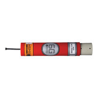
Wideband Sub-Mini Transponder / Responder (WSM6)
Brand:
Sonardyne
| Category:
Marine Radio
| Size: 20 MB
Table of Contents
Contacting the Sonardyne Support Team
3
Table of Contents
5
Figures
9
Amendment History
13
Section 1 - Introduction
15
Introduction
15
Related Publications
15
Table 1-1 - Related Publications
15
Section 2 - Safety
17
Introduction
17
Procedures
17
Section 3 - Technical Description
19
Introduction
19
Description
19
Figure 3-1 - Type 8270 Directional Wideband Sub-Mini 6G
19
Figure 3-2 - Type 8270 Directional Wideband Sub-Mini 6G® Outline Drawing
19
Figure 3-3 - Type 8271 Omni-Directional Wideband Sub-Mini 6G
20
Figure 3-4 - Type 8271 Omni Directional Wideband Sub-Mini 6G® Outline Drawing
20
Figure 3-5 - Type 8270 Directional Wideband Sub-Mini 6G® End-Cap
20
Figure 3-6 - Type 8271 Omni Directional Wideband Sub-Mini 6G® End-Cap
21
Figure 3-7 - Connector End-Cap
22
Figure 3-8 - Connector Pin Numbering
23
Wsm6
24
Figure 3-9 - Type 8271-000-07 1000M Rated Omni-Directional WSM6 with Connector for Remote Transducer
25
Figure 3-10 - Type 8271-000-07 - 1000M Rated Omni-Directional WSM6 with Straight Remote Transducer
26
Figure 3-11 - Type 8271-000-07 - 1000M Rated Omni-Directional WSM6 with Right-Angle Remote Transducer
27
Figure 3-12 - Type 8065-120-XM 1000M Rated Straight Remote Transducer
28
Figure 3-13 - Type 8065-121-XM 1000M Rated Right-Angle Remote Transducer
29
Configuration
30
Table 3-1 - Type 8270 WSM6 Configuration Table
30
Table 3-2 - Type 8271 WSM6 Configuration Table
30
Battery Charging Description
31
Fast Charging
32
Figure 3-14 - Charger Connections
32
Compatibility with SSM Chargers
33
Variants
33
8270-000-11 Wsm6
33
Figure 3-15 - 8270-000-11 Connector Pin-Out
33
8270-000-07 Wsm6
34
Figure 3-16 - 8270-000-07 Connector Pin-Out
34
Section 4 - Installation
35
Pre-Use Checks
35
Check the Pressure Relief Vent Valve
35
Figure 4-1 - WSM6 Pressure Relief Vent Valve and Connector Location
35
Charge the Battery
36
Figure 4-2 - WSM6 ON/OFF Switch
37
Section 5 - Operation
39
Operational Modes
39
Transponder Mode
39
Figure 5-1 - Overall Acoustic Sequence HPR - 300 Series Channels
40
Figure 5-2 - Overall Acoustic Sequence HPR - 400 Series Channels
40
Responder Mode
41
Preparing the WSM6 for Service
41
Check the Pressure Relief Vent Valve
41
Figure 5-3 - HPR Responder Sequence
41
Charge the Battery
42
Set the Interrogation Channel and Command Address
42
Transmission Power Level
42
Receiver Gain Level
42
Enable Depth Telemetry
42
Location on ROV
43
Switch on and Electrical Connections
43
Test the Transponder
43
After Use
44
Acoustic Command Functions
44
Interrogators
45
Wideband Interrogators
45
Figure 5-4 - Connector Pin-Out and Mating Tail
46
Figure 5-5 - Mating In-Line Female Connector (Part No. 820-5163)
46
Wideband Sub-Mini 6 - Pre-Deployment Checklist
47
Table 5-1 - Wideband Sub-Mini 6 - Pre-Deployment Checklist
47
Section 6 - Maintenance & Monitoring
49
Maintenance
49
General Maintenance
49
Inspection
49
WSM6 Battery Charging Procedure
49
Corrosion Removal
50
Dismantling
51
Figure 6-1 - Retaining Rod
52
Removal of the Battery Pack
54
Removal of CPU Boards
54
End-Cap Connector Tightening Procedure
54
Lubrication
55
Lubrication of Subconn and Micro-Subconn Connectors
55
Assembly Procedure
55
Figure 6-2 - Type 8270 / 8271 Wideband Sub-Mini 6 Assembly
57
Figure 6-3 - Circuit Block Diagram
58
Section 7 - WSM6 Functional Test
59
WSM6 Functional Test
59
Serial Communications with PC Software
59
Figure 7-1 - WSM Terminal Software Get Status
59
Transponder Test
60
WSM Terminal Test Software
60
Introduction
60
Software Installation
61
Electrical Connections
61
Figure 7-2 - Transponder Connection Configuration for Software Installation
61
Software Operation
62
Software Setup Procedure
62
Figure 7-3 - Software Operation
62
Serial Port Settings
63
Figure 7-4 - Serial Port Settings
63
General Status
64
Figure 7-5 - Get Status Current Configuration
64
Table 7-1 - WSM Terminal General Status Meanings
65
NAV Scheme
66
Quickset Wideband® 1
66
Figure 7-6 - Quickset Wideband Setting
66
Figure 7-7 - Quickset Wideband Configuration
67
Quickset Wideband® 2
68
Figure 7-8 - Quickset Wideband® 2 Setting
68
Figure 7-9 - Quickset Wideband® 2 Configuration
69
Sonardyne Tone
70
Figure 7-10 - Sonardyne Tone Setting
70
Figure 7-11 - Mouse Prompt Display
71
Hpr
72
Figure 7-12 - HPR Set up
72
Battery Status
73
Depth Telemetry
73
Figure 7-13 - Depth Settings
73
Transponder Settings
74
Figure 7-14 - Depth On/Off Settings
74
Figure 7-15 - General Settings - HPR
75
Figure 7-16 - General Settings - Address
76
Figure 7-17 - General Settings Sonardyne Interrogate
77
Release
78
Firmware Upgrade Download
78
Figure 7-18 - Download Password Prompt
78
Figure 7-19 - Firmware Download
79
Download Settings
80
Figure 7-20 - Firmware Download File Selection
80
Downloading
81
Figure 7-21 - Download Settings
81
Figure 7-22 - Firmware Downloading Status
82
Figure 7-23 - Firmware Download Complete
82
Checking a Successful Download
83
Downloading to an Already-Erased Transponder
83
Figure 7-24 - Listening for Transponder Message
84
Transponder Testing
85
Diagnostics - Responder Trigger (Ping) Test
85
Figure 7-25 - Listening for Transponder Download
85
Diagnostics - Channel Range Test Using an ANT
86
Figure 7-26 - Ping Test
86
Figure 7-27 - Channel Range Test Using ANT
86
Figure 7-28 - Select Channel(S) to Test
87
Figure 7-29 - New Test Channel File
88
Figure 7-30 - before Setting Path and File Name
88
Figure 7-31 - with Path and File Name Set
89
Figure 7-32 - Select Channel(S) to Test after Entering Desired Channel File
89
Figure 7-33 - Saving File and Resulting Screens
90
Figure 7-34 - Saved Channel Results
90
Name of Test (Optional)
91
Figure 7-35 - Highlighting a Channel to Delete from Channel(S) to Test List
91
Saving
92
Check Boxes
92
Figure 7-36 - Saving File Already Exists Prompt
92
Figure 7-37 - Test Title Dialog Box
92
Figure 7-38 - Setting ANT Parameters
93
Figure 7-39 - ANT Parameters
93
Running the Test
94
Figure 7-40 - Channel Testing Range
94
Diagnostics - Channel Depth Test
95
Figure 7-41 - Channel Depth Test Range
95
Diagnostics - Transponder to Transponder Test
96
Figure 7-42 - Failure to Turn on Depth Sensor
96
Figure 7-43 - Transponder Not Supported Window
96
Diagnostics - Reset Transponder
97
About
97
Figure 7-44 - Write HPR Channel
97
Figure 7-45 - HPR Channel Written
97
Figure 7-46 - Sonardyne about Screen
97
Programming the Acoustic Navigation Tester (ANT)
98
Figure 7-47 - Products Supported
98
Tone Burst Sequence
99
Table 7-2 - ANT Keypad Sequence of Operation
99
Responder Trigger Sequence
100
Table 7-3 - Responder Trigger Sequence
100
HPR Channel Test
101
Table 7-4 - HPR Channel Test
101
Acoustic Command Test
102
Table 7-5 - Acoustic Command Test
102
Section 8 - Fault Diagnosis
103
Introduction
103
Test Equipment
103
Quick Voltage Checks
103
Diagnostic Set-Up
103
Figure 8-1 - Test Configuration
104
Diagnostic Procedures
105
Quiescent Checks
105
Quiescent Current
105
Supply Voltage
105
Regulator Output
105
Figure 8-2 - Tx/Rx Board 8270-035
106
100Khz Oscillator
107
CPU Operation
107
24V Input Test
107
Figure 8-3 - CPU Board 8270-036
107
Functional Check
108
Transponder Mode
108
Figure 8-4 - Functional Test Configuration
108
Pre-Amplifier First Stage Output
110
Figure 8-5 - Pre-Amp 1 St Stage Waveform
110
Squarer Stage Output
111
Envelope Detector Output
111
Figure 8-6 - Pre-Amp 2 Nd Stage Waveform
111
Figure 8-7 - Comparator O/P Waveform
111
IIFDET and TXPW Output
112
IIFDET and TXEN Output
112
Figure 8-8 - IIFDET and TXPW Waveform
112
Figure 8-9 - IIFDET and TXEN Waveform
112
Drive Amplifier Input
113
Drive Amplifier O/P Output
113
Figure 8-10 - Drive Amp I/P Waveform
113
Figure 8-11 - Drive Amp O/P Waveform
113
Responder Mode
114
Figure 8-12 - O/P from Coupling Loop
114
Acceptance Test
115
Battery off Load Voltage
115
Battery Charge Circuit Function
115
Serial Communications with PC Software
115
Transponder Test
115
Acoustic Command Test
116
Responder Trigger Test
116
Current Demand Test
116
Trickle Charge Function
117
Wideband Test
117
Section 9 - Retrieval and Storage
119
Retrieval and Storing
119
Section 10 - Spares
121
10. Introduction
121
Type 8270 Wideband Sub-Mini 6G: Directional 4000 Metres
121
Table 10-1 - Type 8270 WSM6 Component Identification Table
121
Type 8271 Wideband Sub-Mini 6G: Omni-Directional 1000 Metres
123
Table 10-2 - Type 8271 Wideband Sub-Mini 6G: Omni-Directional 1000M
123
Type 8270-000-11 - Wideband Sub-Mini Directional 6G 4000M, 5-Pin Female
125
Table 10-3 - TYPE 8270-000-11 Wideband SUB-MINI Directional 6G 4000M, 5-Pin FEMALE Spares and Accessories
125
Type 8270-000-07 Wideband Sub-Mini 6G Directional 4000M 8-Pin
127
Table 10-4 - Type 8270-000-07 Wideband Sub-Mini 6 Directional 6G 4000M 8-Pin Spares and Accessories
127
Section 11 - Technical Specifications
129
Technical Specification for Type 8270 / 8271 Wideband Sub-Mini 6G
129
Figure 11-1 - Connector Pin Numbering
131
Glossary of Terms
133
Appendix A - Firmware History
135
Table 11-1 - Firmware History
135
Appendix B - Frequency Tables
136
B Frequency Tables
136
B.1 HPR - 300 Frequency Table
136
B.2 HPR - 400 Frequency Table
137
B.3 Sonardyne Tone / Frequency Interrogations
138
B.4 Sonardyne Wideband Replies
138
Advertisement
Advertisement
Related Products
Sonardyne 8300
Sonardyne 8270
Sonardyne 8221 HPT
Sonardyne 8212 HPT
Sonardyne 8084-6510
Sonardyne 8142-000-01
Sonardyne 8142-000-02
Sonardyne 8182-000-01
Sonardyne 8142 HPT
Sonardyne 8182 HPT
Sonardyne Categories
Marine Radio
Transceiver
Marine Equipment
Accessories
Test Equipment
More Sonardyne Manuals
Login
Sign In
OR
Sign in with Facebook
Sign in with Google
Upload manual
Upload from disk
Upload from URL