Sign In
Upload
Manuals
Brands
Solid Manuals
Network Hardware
EXPRESS Single-Carrier DAS
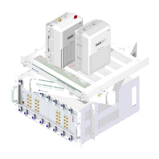
Solid EXPRESS Single-Carrier DAS Solution Manuals
Manuals and User Guides for Solid EXPRESS Single-Carrier DAS Solution. We have
1
Solid EXPRESS Single-Carrier DAS Solution manual available for free PDF download: Installation And Operation Manual
Solid EXPRESS Single-Carrier DAS Installation And Operation Manual (136 pages)
Brand:
Solid
| Category:
Network Hardware
| Size: 9 MB
Table of Contents
Table of Contents
3
Introduction
11
Intended Audience
11
Document Conventions
11
Getting Support
11
Safety and EMC Approvals
12
Safety Precautions
12
Overview and Specifications
13
Features
14
System Components
14
Figure 2.1 - EXPRESS Distributed Antenna System (DAS) Topology
15
SISO Configuration
16
Figure 2.2 - EXPRESS das - SISO Configuration
16
MIMO Configuration
17
VHF/UHF Support
17
Figure 2.3 - EXPRESS das - MIMO Configuration
17
Figure 2.4 - EXPRESS das - VHF/UHF Configuration
17
System Capacities
18
Mechanical Specifications
19
Table 2.1 - Mechanical Specifications for BIU, ODU, OEU
19
Environmental Specifications
20
Table 2.2 - Mechanical Specifications for MRU, ARU, VHF/UHF AOR
20
Table 2.3 - Environmental Specifications
20
Optic Specifications
21
Frequency Bands
21
Table 2.4 - Optic Wavelength and Laser Power
21
Table 2.5 - Frequency Bands
21
Band Specifications
22
Output Power Level
22
RF Specifications
22
Table 2.6 - Output Power Level by Band
22
Table 2.7 - RF Specifications
22
BTS Interface Unit (BIU)
23
Figure 3.1 - BIU Block Diagram
23
BIU Specifications
24
Figure 3.2 - BIU Dimensions
24
BIU Mechanical Specifications
25
BIU Environmental Data
25
Table 3.1 - BIU Mechanical Specifications
25
Table 3.2 - BIU Environmental Data
25
BIU Components
26
Figure 3.3 - BIU Components
26
Table 3.3 - BIU Components and Functions
26
Table 3.4 - BIU Components -- Power Consumption, Weight and Dimension
27
Main Drive BTS Unit (MDBU)
28
Figure 3.4 - MDBU at a Glance
28
Table 3.5 - MDBU Supported Bands and Frequencies
29
Main Combiner Divider Unit (MCDU)
30
Figure 3.5 - MCDU at a Glance
30
Table 3.6 - MCDU - VHF/UHF Frequency Band
30
Main Central Processor Unit (MCPU)
31
Figure 3.6 - MCPU at a Glance
31
Main Power Supply Unit (MPSU)
32
Figure 3.7 - MPSU at a Glance
32
BIU Front / Rear Panel - Indicators and Connectors
33
Figure 3.8 - BIU Front Panel
33
Table 3.7 - BIU Front Panel Indicators
33
Figure 3.9 - BIU Rear Panel
34
Table 3.8 - BIU Rear Panel Connectors
34
EXPRESS DC Power Supply (SC-RMP-480)
35
SC-RMP-480 Features
35
SC-RMP-480 Specifications
35
Figure 3.10 - DC Power Supply Front View
35
Table 3.9 - DC Power Supply Specifications
35
Optical Distribution Unit (ODU)
36
Figure 4.1 - ODU Block Diagram
36
ODU Specifications
37
Figure 4.2 - ODU Dimensions
37
ODU Mechanical Specifications
38
ODU Environmental Data
38
Table 4.1 - ODU Mechanical Specifications
38
Table 4.2 - ODU Environmental Data
38
ODU Components
39
Table 4.3 - ODU Components
39
Table 4.4 - ODU Components - Mechanical Specifications
39
Donor Optic Unit (DOU)
40
Figure 4.3 - DOU at a Glance
40
Donor Optic Unit Specifications
41
Optical Data
41
Electrical Data
41
Table 4.5 - DOU Optical Data
41
Table 4.6 - DOU Electrical Data
41
ODU Front / Rear Panel - Indicators and Connectors
42
Figure 4.4 - ODU Front Panel
42
Figure 4.5 - ODU Rear Panel
42
Table 4.7 - ODU Front Panel Indicators
42
Table 4.8 - ODU Rear Panel Connectors
42
Remote Units - MRU, ARU, VHF/UHF AOR
43
Figure 5.1 - MRU/ARU Block Diagram
43
MRU/ARU Specifications
44
Figure 5.2 - MRU/ARU Dimensions
44
MRU/ARU Mechanical Specifications
45
MRU/ARU Environmental Data
45
Table 5.1 - MRU/ARU Mechanical Specifications
45
Table 5.2 - MRU/ARU Environmental Data
45
MRU/ARU Mechanical Specifications
46
Table 5.3 - MRU/ARU Mechanical Specifications
46
MRU RF Specifications
47
Table 5.4 - MRU RF Specifications
47
ARU RF Specifications
48
Table 5.5 - ARU RF Specifications
48
MRU/ARU Components
49
Figure 5.3 - MRU 850C+1900P Internal View
49
Table 5.6 - MRU / ARU Components
49
Main RF Module/Add-On RF Module (MRFM/ARFM) and Band Pass Filters
50
Remote Power Supply Unit (RPSU)
50
Table 5.7 - Main RF Module/Add-On RF Module (MRFM/ARFM) and Band Pass Filters
50
Table 5.8 - Remote Power Supply Unit - Range of Input Power
50
Remote Optic (R-OPT)
51
Remote Central Processor Unit (RCPU)
51
MRU/ARU Connectors (Top / Bottom Views)
52
MRU/ARU Top View
52
Figure 5.4 - MRU / ARU Top Connectors
52
Table 5.9 - MRU / ARU Top Connectors
52
MRU/ARU Bottom View and Connectors
53
Figure 5.5 - MRU / ARU Bottom Connectors
53
Table 5.10 - MRU / ARU Bottom Connectors
53
MRU / ARU Power Ports
54
Figure 5.6 - MRU / ARU Power Connectors
54
VHF/UHF AOR Specifications
55
Figure 5.7 - VHF/UHF AOR at a Glance
55
Table 5.11 - VHF/UHF AOR Mechanical Specifications
55
Band Specifications 150Mhz VHF Public Safety
56
Band Specifications 450Mhz UHF Public Safety
56
Table 5.12 - Band Specifications 150Mhz VHF Public Safety
56
Table 5.13 - Band Specifications 450Mhz UHF Public Safety
56
VHF/UHF AOR Components
57
AOR Remote Drive Unit (RDU)
57
Figure 5.8 - VHF/UHF AOR Internal View
57
Table 5.14 - VHF/UHF AOR Components
57
AOR Power Supply Unit (PSU)
58
AOR System Interface Unit (SIU)
58
VHF/UHF AOR Rear View Connectors
58
Figure 5.9 - VHF/UHF AOR Rear View Connectors
58
Table 5.15 - VHF/UHF AOR Connectors
58
VHF/UHF AOR Power Ports and External Ports
59
Figure 5.10 - AOR Power Port
59
Figure 5.11 - AOR External Port
59
Optic Expansion Unit (OEU)
60
Figure 6.1 - OEU Block Diagram
60
OEU Specifications
61
OEU Environmental Data
61
Figure 6.2 - OEU Dimensions
61
Table 6.1 - OEU Environmental Data
61
OEU Mechanical Specifications
62
Table 6.2 - OEU Mechanical Specifications
62
OEU Components
63
Figure 6.3 - OEU Internal View
63
OEU Components - Mechanical Specifications
64
Table 6.3 - OEU Components
64
Table 6.4 - OEU Components - Mechanical Specifications
64
Donor Optic Unit
65
Extension Wavelength Division Multiplexer (EWDM)
65
Expansion Central Processor Unit (ECPU)
65
Expansion Radio Frequency Module (ERFM)
65
Expansion Power Supply Unit (EPSU)
65
OEU Front / Rear Panel - Indicators and Connectors
66
Figure 6.4 - OEU Front Panel
66
Figure 6.5 - OEU Rear Panel
66
Table 6.5 - OEU Front Panel Indicators
66
Table 6.6 - OEU Rear Panel Connectors
66
DAS Management System (DMS-600)
67
Figure 7.1 - das Management with DMS-600
67
Specifications
68
Figure 7.2 - DMS-600 at a Glance
68
Table 7.1 - DMS-600 Specifications
68
Front / Rear Panel - Indicators and Connectors
69
Figure 7.3 - DMS-600 Front Panel
69
Figure 7.4 - DMS-600 Rear Panel
69
Table 7.2 - DMS-600 Front Panel Indicators
69
Table 7.3 - DMS-600 Rear Panel Connectors
69
Installation - Headend Equipment: BIU, Power Supply, ODU, DMS-600
70
Before You Begin
70
Table 8.1 - Tools and Accessories for Installing Headend Equipment
71
Install BIU Chassis
72
Install DC Power Shelf and Connect to BIU
72
Figure 8.1 - BIU Rack Installation
72
Figure 8.2 - BIU Terminal Block
73
Figure 8.3 - MPSU LED Indicators
73
BIU Power Consumption
74
Table 8.2 - BIU Power Consumption
74
Installing Additional Mdbus
75
Figure 8.4 - MDBU Installation
75
Connect BIU to the RF Source - BTS or BDA
76
Table 8.3 - Port Assignments for Connecting Input and Output to RF Source
76
Figure 8.5 - BIU RF Interface Diagram
77
Connecting the BIU to a BTS
78
Figure 8.6 - BTS Interface to the BIU Backplane
78
Connecting the BIU with BDA
79
Figure 8.7 - BDA Interface to the BIU Backplane Using a Duplexer
79
Checking Power and RF Signaling
80
Figure 8.8 - MDBU LED Indicators and SMA Test Ports
80
Install Optical Drive Units (Odus)
81
Figure 8.9 - ODU Rack Installation
81
Connect ODU to BIU for Power and Signaling
82
Figure 8.10 - BIU RF and Signaling Ports
82
Figure 8.11 - Connecting the BIU to ODU(S)
83
ODU Power Consumption
84
Installing Dous
84
Figure 8.12 - ODU Showing One and Two DOU Configurations
84
Table 8.4 - ODU Power Consumption
84
Connecting ODU Optic Cabling
85
Installing the DMS-600
85
Figure 8.13 - SC/APC Fiber Terminations
85
Installation - OEU
86
Before You Begin
86
Table 9.1 - Accessories and Tools List for OEU Installation
86
Install OEU Chassis
87
Install DC Power Shelf and Connect to OEU
87
Figure 9.1 - OEU Terminal Block
87
OEU Power Consumption
88
Installing Dous
88
Figure 9.2 - OEU Showing One and Two DOU Configurations
88
Table 9.2 - OEU Power Consumption
88
Connecting the OEU to ODU(S)
89
Figure 9.3 - Connecting the OEU to ODU
89
Installation - MRU and ARU
90
Before You Begin
90
Table 10.1 - Tools and Accessories for Installing Mrus/Arus
90
Install MRU/ARU Enclosures - Wall Mount
91
MRU/ARU Wall Mount - Side-By-Side Installation
91
Figure 10.1 -MRU a Nd a RU D Imensions
91
Figure 10.2 - Side-By-Side Wall Mount Installation for the MRU / ARU
92
MRU/ARU Wall Mount - Stacked Installation
93
Figure 10.3 - Dimensions of Stacking Bracket
93
Figure 10.4 - Stack Mounting the MRU/ARU
94
MRU/ARU Rack Mount - Vertical Installation
95
Figure 10.5 - Dimensions for MRU/ARU Vertical Rack Installation
95
Figure 10.6 - M RU/ARU Installation Procedure for Vertical Rack
96
MRU/ARU Rack Mount - Horizontal Installation
97
Figure 10.7 - Dimensions for MRU/ARU Horizontal Rack Installation
97
Connect MRU / ARU Power
98
Figure 10.8 - MRU/ARU Installation Procedure for Horizontal Rack
98
Figure 10.9 - MRU / ARU Power Ports - AC/DC and DC/DC
98
MRU/ARU Power Consumption
99
Table 10.2 - MRU/ARU Power Consumption
99
Connect Ground Terminal
100
Figure 10.10 - MRU / ARU Ground Terminal
100
Connect Optical Cabling
101
Figure 10.11 - Attaching Fiber Optic Cabling to the MRU
101
Connect MRU and ARU
102
Figure 10.12 - Connecting the MRU to the ARU
102
Connect Coaxial Cable and Antenna
103
Table 10.3 - MRU/ARU Cable Connections
103
Power on MRU / ARU and Check Status
104
Table 10.4 - MRU LED Indicators
104
Installation - VHF/UHF Add-On Remote
105
Before You Begin
105
Table 11.1 - Tools and Accessories for Installing VHF/UHF Add-On Remote
105
Installing the VHF/UHF AOR - Wall Mount
106
Figure 11.1 - Recommended Clearances for VHF/UHF AOR Wall Mounting
106
Figure 11.2 - VHF/UHF AOR Wall Mount Dimensions
107
Figure 11.3 - Wall Mounting the AOR
107
Installing the VHF/UHF AOR - Rack Mounting
108
Installing Power Cabling
108
Figure 11.4 - VHF/UHF AOR Power Port
108
Table 11.2 - VHF/UHF AOR Power Connections
108
VHF/UHF AOR Power Consumption
109
Connecting Ground (GND) Terminal
109
Figure 11.5 - VHF/UHF AOR Ground Port
109
Table 11.3 - VHF/UHF AOR Power Consumption
109
Connecting the Add-On Unit to the MRU
110
Figure 11.6 - Connecting the MRU to VHF/UHF AOR
110
Table 11.4 - VHF/UHF AOR / MRU Connections
110
Connecting Coaxial Cable and Antennas
111
Powering on Add-On Unit and Checking Status
111
Figure 11.7 - Power and Alarm Indicators for AOR
111
System Commissioning
112
Before You Begin
112
Table 12.1 - Tools and Accessories for System Commissioning
112
Connect DMS-600 to EXPRESS das
113
Figure 12.1 - Connecting Laptop to DMS-600
113
Open Management Software and Run Easyset
114
Figure 12.2 - Management Software Home Screen
114
Changing Factory Defaults
115
Figure 12.3 - Easyset Progress Bar
115
Figure 12.4 - System Setup Screen
116
Manual Setup
117
Load the Command & Control Menu
117
Figure 12.5 - Command & Control Screen
117
Verify All Connections
118
Set MDBU Parameters
118
Figure 12.6 - Setting MDBU Parameters
118
Set Optic Compensation
119
Figure 12.7 - Setting Optic Values
119
Table 12.2 - Optic Compensation
120
Set MRU/ARU Parameters
121
Figure 12.8 - Configuration Screen
121
System Acceptance
122
Validating the Uplink Path
123
Figure 12.9 - Validating the Uplink Path
123
Table 12.3 - Recommended Test and Link Budget Values Per Band for Uplink Path
123
Validating the Downlink Path
124
Figure 12.10 - Validating the Downlink Path
124
Table 12.4 - Recommended Test and Link Budget Values Per Band for Downlink Path
124
Alarm Troubleshooting
125
ODU Alarm Troubleshooting
125
Table 12.5 - Alarm Indicators in Management Software
125
Table 12.6 - ODU Alarm Indicators in Management Software
125
BIU Alarm Troubleshooting
126
Table 12.7 - BIU Alarm Indicators in Management Software
126
MRU Alarm Troubleshooting
127
Table 12.8 - MRU Alarm Indicators in Management Software
127
OEU Alarm Troubleshooting
128
Table 12.9 - OEU Alarm Indicators in Management Software
128
Appendix - Additional Functions
129
Shutdown Function (Tx Output Shutdown)
129
Total Power Limit Function (Tx Output ALC)
129
Automatic Output Power Setting Function (Tx Output AGC)
130
Input Power AGC Function (Tx Input AGC)
130
Table 13.1 - Attenuation (ATT) Level Values
130
Input Power Limit Function (Tx Input ALC)
131
Optic Loss Compensation
131
Figure 13.1 - Optical Loss Information
131
Appendix - EXPRESS Part Numbers
132
Table 14.1 - BIU Part Numbers
132
Table 14.2 - ODU/OEU Part Numbers
132
Table 14.3 - MRU and ARU Part Numbers
133
Table 14.4 - DMS-600 Part Numbers
133
Table 14.5 - Link Balancer Unit Part Numbers
134
Appendix - Glossary of Terms
135
Advertisement
Advertisement
Related Products
Solid Alliance eROU
Solid Alliance eROUa
Solid GENESIS DAS
Solid RocketWAVE SRF-L-1835
Solid Categories
Garden Houses
Outdoor Furnishing
Network Hardware
Speakers
Lawn and Garden Equipment
More Solid Manuals
Login
Sign In
OR
Sign in with Facebook
Sign in with Google
Upload manual
Upload from disk
Upload from URL