Sign In
Upload
Manuals
Brands
Smiths Medical Manuals
Medical Equipment
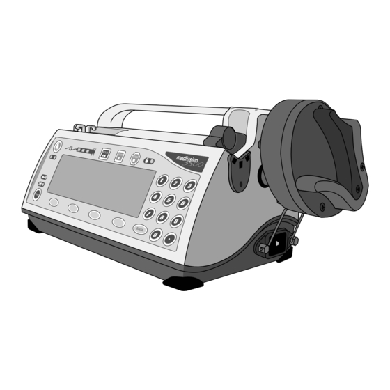
Medfusion 3000 Series
Smiths Medical Medfusion 3000 Series Pump Manuals
Manuals and User Guides for Smiths Medical Medfusion 3000 Series Pump. We have
1
Smiths Medical Medfusion 3000 Series Pump manual available for free PDF download: Technical & Service Manual
Smiths Medical Medfusion 3000 Series Technical & Service Manual (184 pages)
Brand:
Smiths Medical
| Category:
Medical Equipment
| Size: 3 MB
Table of Contents
Table of Contents
3
I Introduction
7
Important Information
7
Warnings
7
Cautions
8
Contents of this Manual
9
Authorized Use of this Manual
9
About the Pump
10
Features and Controls
10
Keypad Closeup
11
Understanding "Biomed" Mode
13
What Is Biomed
13
Authorized Biomed Access
13
Biomed Software Program - Major Options
13
Symbols
14
Glossary of Technical Terms
15
Scheduled Maintenance
21
Preventive Maintenance Planning
21
Biomed Maintenance Tools
21
Using a Torque Screwdriver
21
Electrostatic-Controlled Workstation
21
Service Warnings
22
Periodic Maintenance
23
Installation/Quick Check-Out
23
Quick Check-Out Test
23
Cleaning and Care
24
Standard Cleaning of Medfusion™ 3000 Series Pumps
24
Cleaning Cautions
24
Mandatory Annual Maintenance Testing
25
General Inspection
25
Power-Up Test
25
Calibration Verification
26
Force Sensor Check
26
Syringe Size Sensor Check
26
Plunger Position Sensor Check
27
Motor Drive & Occlusion Operational Test
27
Flow Delivery Accuracy Test
28
AC Line Leakage Test
28
AC Line Leakage Test - Medfusion™ 3500BC
29
Battery Maintenance
30
Shallow Discharge (CPI) Record
30
Battery Calibration Procedure
30
Requirements for Battery Pack Replacement
31
Collect Separately
31
Theory of Operation
33
Overview of Operation
33
Controlling Motor Functions
33
Infusion Control & Safety Functions
33
Pump Design Description
34
Logic Core of Medfusion™ 3000 Series Pumps
34
Main Circuit Board
34
Main Microprocessor
34
Watchdog Circuit
35
DC Power Converter
35
Real Time Clock
35
Graphical Display Circuit Board (LCD)
35
Keypad
35
Plunger (Driver) Travel Sensor
35
Motor Rotation Sensor
35
Stepper Motor
35
Syringe Flange Loaded Sensor
35
Syringe Size Sensor
35
AC Power Input & Power Supply Board
36
DC Power Input Jack
36
Speaker
36
Rechargeable Battery Pack & Battery Gauge
36
Plunger Printed Circuit Board
36
Plunger Force Sensor
36
Plunger Loaded Sensors
36
Main Board - Schematic Level
37
Logic Kernel Description
37
68HC11K4 Main Microprocessor Interface, U19
37
Software Upgrade Method for Programming Flash Memory
40
Static Random Access Memory, U17
40
Serial EEPROM, U2 and U4
40
Time of Day, U8
40
Infrared Transceiver
40
Analog to Digital Converter, U13
41
Digital to Analog Converter, U20
41
I/O Port Expansion, U3, U33
42
Expansion Port # 1 (Port1_Cs)
42
Expansion Port # 2 (Port2_Cs)
43
Power Control Description
44
Always on Supply, U7
44
Backup Super Capacitor, C11
44
Backup Audio Buzzer, XD1
44
System Reset, U43
45
Power Management, U39
45
Power off State
45
Power on State
45
Watchdog
45
DC to DC Converter
46
Logic Supply, U12
46
Motor Supply, U34
46
Analog Supply, U21
46
Positive & Negative Supply, U36
47
LCD Backlight Supply, U1
47
Front Panel Interface Description
48
LED Drive Circuit, Q26, Q27, Q40, Q33 - Q37
48
Keypad Matrix Interface
48
Power Switch Interface
48
Graphic Display Interface Description
49
Data Output to LCD, U32 / Data Input from LCD, U6
49
LCD Contrast
49
LCD Backlight
49
Motor Drive Description
50
Coil a & B PWM Current References
50
Motor Current Regulators, U26, U35
50
Motor Current Detector, U40
50
Sensors Interface Description
51
Motor Speed Detection
51
Syringe Sensing Description
51
Syringe Size Sensing
51
Syringe Flange (Ear) Sensing
51
Plunger Position Sensing Description
52
Speaker Drive Description
52
Speaker Control
52
Speaker Test
53
Plunger Board - Schematic Level
53
Force Preamplifier Function
53
Force Sensing Interface Description
53
Plunger Flipper Sensor Function
54
Interconnect Board - Schematic Level
55
AC Power Detection Description
55
External DC Power Conditioning / Detection Description
56
Infrared Serial Data Port Description
56
Battery Management Description
57
Battery Gauge Interface
57
Battery Charger
57
Charge Detector
58
Battery Switchover
58
Battery Board - Schematic Level
58
Battery Gauge Function
58
Severely Depleted Battery Monitor
58
Troubleshooting
59
Problem Solving Alarms / Alerts
59
Types of Alarms / Alerts
59
Alarm Messages & Priorities
60
System Advisory Alarms
66
System Failure Alarms
67
General Troubleshooting
71
Smiths Medical Service and Support
73
Using Smiths Medical Service Assistance
73
Returning a Pump for Repair
73
Using B Iomed for Troubleshooting
74
Accessing Biomed
74
Biomed > Calibration
75
Biomed > Diagnostics (Screen 1 of 2)
75
Audio Test
75
Display Test
75
Indicator Test
75
Keypad Test
76
Monitor Analog Sensors
76
Monitor Digital Sensors
76
Monitor Battery Status
76
Drive Train Test
76
Biomed > Diagnostics (Screen 2 of 2)
76
Motor Drive Test
77
Monitor A2D Selftest
77
Monitor 6811 A2D Group1
77
Monitor 6811 A2D Group2
77
Biomed > Utilities
77
Set/View Last [Next] PM Date
77
Versions
77
Set Time/Date (Current)
78
View Alarm History
78
View Infusion History
78
View Service Data
78
View EEPROM Size
78
3500 Pumps Version 4 and Higher)
78
Biomed > Update Firmware
79
Medfusion™ 3500 Pumps, Version 4 and Higher]
79
Set Language [Not Available on Medfusion™ 3010 and 3010A]
79
Parts Replacement
81
Maintenance Warnings/Cautions
81
Service Warnings
81
Service Cautions
81
Opening & Closing the Pump Housing
82
Tools Needed
82
Opening the Pump Housing
82
Closing the Pump Housing
82
Battery Pack
83
Tools Needed
83
Removing the Battery Pack
83
Replacing the Battery Pack
83
Verifying Battery Function after New Battery Replacement
83
Interconnect Board
84
Tools Needed
84
Removing the Interconnect Board
84
Replacing the Interconnect Board
84
Verify Interconnect Board Function
84
Speaker
84
Speaker Removal
84
Speaker Replacement
84
Verifying Speaker Function
84
AC Power Supply
85
Tools Needed
85
Removing AC Power Supply
85
Replacing the AC Power Supply
85
Verify AC Power Supply Function
85
AC Input Assembly
85
Removing AC Input Module Assembly
85
Replacing AC Input Module Assembly
85
Verifying AC Input Assembly Module Function
86
Bottom Housing Plastic
86
Tools Needed
86
Removing the Bottom Housing
86
Replacing the Bottom Housing
86
Main Board
87
Tools Needed
87
Removing the Main Board
87
Replacing the Main Board
87
Drive Train Assembly
88
Tools Needed
88
Motor Unit (Motor, Worm, Worm Gear)
88
Removal
88
Replacement
88
Reassemble Motor Unit
88
Position Potentiometer
89
Removal
89
Replacement
89
Clutch Assembly
90
Tools Needed
90
Leadscrew
90
Removal
90
Replacement
90
Clutch or Clutch Cam
90
Removal
91
Replacement
91
Plunger Cable
91
LCD and Backlight
92
Tools Needed
92
Removing LCD And/Or Backlight Assembly
92
Replacing the LCD And/Or Backlight Assembly
92
Verify LCD & Backlight Assembly Function
93
Keypad
93
Tools Needed
93
Removing the Keypad
93
Replacing the Keypad
94
Syringe Barrel Clamp Assembly
94
Tools Needed
94
Barrel Clamp Head
94
Removal
94
Replacement
94
Verify Function
94
Barrel Clamp Body Assembly
94
Replacement
95
Ear Clip, Handle & Guide
95
Tools Needed
95
Ear Clip
95
Removal
95
Ear Clip Optical Sensor
95
Replacement
96
Handle
96
Removal
96
Tubing Guide
96
Replacement
97
Plunger Case Assembly
97
Tools Needed
97
Plunger Lever
97
Removal
97
Plunger Case Disassembly
97
Disassembly
97
Reassembly
97
Cam Gear and Timing Plate
98
Removal
98
Replacement
98
Flipper and Flipper Gear
98
Plunger Board
98
Additional Tools Needed
98
Replacement
99
Force Sensor
99
Additional Tools Needed
99
Removal
99
Left Plunger Case
100
Additional Tools Needed
100
Removal
100
Replacement
100
Calibration and Adjustment
101
Using B Iomed > C Alibration
101
Biomed > Calibration
101
Calibrate (Syringe) Size and Position
103
Performing both Size & Position Calibration
103
Calibrate Force Sensor
106
Calibrate Pressure Sensor (Future Option)
108
Calibrate Plunger Position
108
Calibrate Syringe Size Sensor
110
Adjust Contrast (Voltage) Setting
111
View Calibration Data
112
Save Changes and Exit
113
Exit Calibration Without Saving Changes
113
Retest Guidelines
114
Schematics & PCB Assemblies
117
System Layout
117
Main Board Schematics
118
Main Board / Logic Kernel
118
Main Board / Power Control Logic Core
122
Main Board / DC-DC Converter
124
Main Board / Keypad Interface
126
Main Board / Graphic Display Interface
129
Main Board / Motor Drive
130
Main Board / Syringe Sensing
131
Main Board / Position Sensing
132
Main Board / Force Sensing
133
Main Board / Pressure Sensing
134
Main Board / Speaker Drive
135
Main Board / ACU-ICE Socket
136
Main Board Assembly Drawing - Top Side
137
Main Board Assembly Drawing - Bottom Side
138
Main Board Assembly - Parts List
139
Plunger Board Schematic
145
Plunger Board / Force Preamplifier
145
Plunger Board / Flipper Sensor
146
Plunger Board Assembly Drawing
147
Plunger Board Assembly - Parts List
148
Battery Gauge Schematic
149
Interconnect Board Schematic
150
Interconnect Board / Power Control
150
Interconnect Board / Battery Management
151
Interconnect Board / Infrared Serial Communications
152
Interconnect Board Assembly Drawing
153
Interconnect Board Assembly - Parts List
154
Assembly Drawings & Parts Lists
157
Assembly Drawings
157
Medfusion™ 3000 Series Main Pump Assembly
158
Medfusion™ 3000 Series Main Pump Assembly - Parts List
159
Case Bottom Assembly
160
Case Bottom Assembly - Parts List
161
Case Top Assembly W/Plunger
162
Case Top Assembly W/Plunger - Parts List
163
Case Top Assembly Without Plunger
164
Case Top Assembly Without Plunger - Parts List
165
Barrel Clamp Assembly
167
Barrel Clamp Assembly - Parts List
168
Drive Train Assembly
169
Drive Train Assembly - Parts List
170
Clutch Assembly
171
Accessories - Parts List
172
Poleclamp Assembly
172
Poleclamp Parts
173
Rotating Poleclamp Parts
173
Miscellaneous Parts
173
Calibration & Repair - Parts List
174
Medfusion™ 3000 Series Calibration Kit
174
Other Tools & Equipment Required to Service Medfusion™ 3000 Series Pumps
174
Advertisement
Advertisement
Related Products
Smiths Medical Oxi-Pulse 30 WW1030
Smiths Medical Medfusion 3500
Smiths Medical Medfusion 3500BC
Smiths Medical CADD-MS 3
Smiths Medical Pneupac 310
Smiths Medical Pneupac 300
Smiths Medical 100/800/060-100
Smiths Medical 100/802/060-100
Smiths Medical 100/810/060-100
Smiths Medical 100/811/060-100
Smiths Medical Categories
Medical Equipment
Water Pump
Food Warmer
Personal Care Products
Pet Care Product
More Smiths Medical Manuals
Login
Sign In
OR
Sign in with Facebook
Sign in with Google
Upload manual
Upload from disk
Upload from URL