Sign In
Upload
Manuals
Brands
SMC Sierra Monitor Manuals
Microphone
5000 Sentry
SMC Sierra Monitor 5000 Sentry Manuals
Manuals and User Guides for SMC Sierra Monitor 5000 Sentry. We have
1
SMC Sierra Monitor 5000 Sentry manual available for free PDF download: Instruction Manual
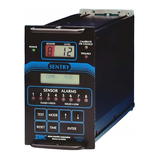
SMC Sierra Monitor 5000 Sentry Instruction Manual (130 pages)
Gas Monitoring System
Brand:
SMC Sierra Monitor
| Category:
Microphone
| Size: 1 MB
Table of Contents
Table of Contents
3
1 Product Description
7
General
7
Controller
7
Enhancement Package
7
Sensor Modules
7
Interconnect Wiring
8
Data Transmission
8
Power Requirements
8
2 Cautions & Warnings
21
Introduction
21
Controller
21
Wiring
21
Sensor Modules - General
21
Combustible Sensor Modules
21
3 Installation
23
Controller Location
23
Sensor Module Locations
23
Wiring
23
Table 3-1 Specific Gravity of Selected Gases
23
Table 3-2 Minimum Wire Gauges
23
Sensor Module Installation
24
Table 3-3 Sensor Module Wiring
24
Table 3-4 Sensor Module Binary Switch Positions
24
Controller Installation
25
Controller Configurations
25
Controller Mounting
25
Table 3-5 Sentry Controller Capacity
25
Table 3-6 Sentry Enclosure Options
25
Alarm Device Installation
26
DC Power Load
26
Relay Outputs
26
Table 3-7 Sentry Power Load
26
Power down
27
Power up
27
4 Configuration Procedure
39
Introduction
39
Start-Up Preparation
39
Configuration Instructions
41
Sentry Training
41
Table 4-1 Display Conditions
42
Sentry Menu
43
Table 4-2 Sentry Primary Menu Selection
43
Test Key
43
Time Key
43
Mode Key - Calib/Change
44
Reset Key
44
Mode Key - Other
45
5 Calibration
53
Sentry Calibration - an Overview
53
Global Calibration
53
Local Calibration
53
Calibration Initialization
53
Modules
53
Calibration Parameters
54
Use MODE
54
Calibration Procedure
54
Controller Set-Up
54
Calibration Gas Delivery Methods
57
Sensor Exposure to Gas
57
Table 5-1 Calibration Gas Flow Rates
57
6 Maintenance
59
Maintenance Requirements
59
7 Service
61
Overview
61
Data Collection
61
General
61
Inspection and Troubleshooting Guide
61
Installation Inspection
61
Inspection Guide
62
Operator Action
62
Troubleshooting Guide
63
Controller
64
Electrical Description
64
Mechanical/Functional Description
64
Communications
69
Description of Communications
69
System Errors
69
Table 7-1 Sentry Error and Diagnostic Messages
69
Access Codes
70
Diagnostic Codes
70
Warm-Up Timers
70
Warning and Error Messages
70
Diagnostic Report
71
Table 7-2 Diagnostic Report Description
71
Hydrogen Sulfide Module (5100-01)
72
Adjustment Procedure
72
Description
72
Trouble Analysis
72
Sensor Replacement
73
Table 7-3 Hydrogen Sulfide Sensor Wiring Pin-Out
73
Table 7-4 Heater Voltage and Current Settings
74
Combustible Gas Sensor Module (5100-02)
75
Adjustment Procedure
75
Description
75
Trouble Analysis
75
Sensor Replacement
76
Table 7-5 Combustible Gas Sensor Wiring Pin out
76
Combustible Gas Scaling Factors
77
Oxygen Module (5100-03)
78
Adjustment Procedure
78
Description
78
Sensor Replacement
78
Trouble Analysis
78
Carbon Monoxide Module (5100-04)
80
Adjustment Procedure
80
Description
80
Trouble Analysis
80
Hydrogen Sulfide Module (5100-05)
82
Adjustment Procedure
82
Description
82
Trouble Analysis
82
Toxic Gas Sensor Module
84
Adjustment Procedure
84
Description
84
Trouble Analysis
84
Sensor Failure
85
Ammonia Sensor Module (5100-25)
87
Adjustment Procedure
87
Description
87
Trouble Analysis
87
8 Appendices
89
Appendix A - Specifications
91
Table 8-1 Toxic Sensor Cross Sensitivity
93
Appendix B - Limited Warranty
95
Appendix C - Access Control by User Code
97
Introduction
97
Definitions
97
User Code Installation
97
User Code Removal
97
Diagnostic Codes
97
Lost Entry Code
98
Appendix D: - Model Numbers & Parts List
99
Controller Items
99
Sensor Module Items
100
Calibration Equipment
101
Identification
103
Capability
103
Reports
103
Appendix E - Instructions for Printer Software Option
103
Periodic Reporting
103
Report Format
104
Change Printer
104
Appendix F - Model 5392 Individual Relay
105
Relay Panel Description
105
Relay Panel Assembly
105
Installation
105
Operation
105
Individual Relay Specifications
105
Table 8-2 Individual Alarm Relay Logic
106
Appendix G - Model 4314 Output Expansion Panel
109
Expansion Panel Description
109
Expansion Panel Assembly
109
Installation
109
Operation
109
Output Expansion Panel Testing
110
Test Alarms
110
Individual Relay Specifications
110
Appendix H - Model 5100-99 Analog Input Module
112
Description
112
Installation
112
Adjustment Procedure
112
Signal Adjustment
112
Appendix I - Model 5100-90 8-Channel
113
Installation
113
Service
113
Appendix I - Model 5100-90 8-Channel Analog-Digital Converter
113
Description
113
Appendix J - Reference Drawings
115
Diagnostic Code
125
9 Index
125
List of Tables
126
10 List of Figures
127
11. List of Tables
128
11 List of Tables
128
Advertisement
Advertisement
Related Products
SMC Sierra Monitor 5100-99-IT
SMC Sierra Monitor Categories
Gateway
Server
Network Router
Network Hardware
Security Sensors
More SMC Sierra Monitor Manuals
Login
Sign In
OR
Sign in with Facebook
Sign in with Google
Upload manual
Upload from disk
Upload from URL