Sign In
Upload
Manuals
Brands
SMC Networks Manuals
Chiller
HRR010-A-20 Series
SMC Networks HRR010-A-20 Series Manuals
Manuals and User Guides for SMC Networks HRR010-A-20 Series. We have
3
SMC Networks HRR010-A-20 Series manuals available for free PDF download: Operation Manual
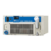
SMC Networks HRR010-A-20 Series Operation Manual (160 pages)
Thermo-chiller
Brand:
SMC Networks
| Category:
Chiller
| Size: 5 MB
Table of Contents
Table of Contents
3
Chapter 1 Safety Instructions
7
Before Using the Product
7
Reading the Manual
7
Hazards
8
Level of Hazards
8
Definition of "Serious Injury" and "Minor Injury
8
Product Label
9
Safety Measures
10
Safety Instructions for Use
10
Personal Protective Equipment
10
Emergency Measures
11
Waste Disposal
12
Disposal of Refrigerant and Compressor Oil
12
Disposal of Product
12
Material Safety Data Sheet (MSDS)
13
Chapter 2 Name and Function of Parts
15
Model Number of Product
15
Air-Cooled Refrigerator Type
15
Water-Cooled Refrigerator Type
16
Name and Function of Parts
17
HRR010-A-20-U (Air Cooled Type)
17
HRR010-W-20-U (Water Cooled Type)
18
Function of Parts
19
Operation Display Panel
20
Chapter 3 Transport and Setting up
21
Transport
21
Installation
22
Environment
22
Location
24
Installation and Maintenance Space
26
Installation
27
Mounting
27
Electrical Wiring
28
Preparation and Wiring of Power Supply Cable
30
Contact Input/Output Communication Wiring
32
Wiring of Run/Stop Signal Input and Remote Signal Input
34
Wiring of Contact Output Signal
35
Communication Wiring
36
RS-232C Communication Wiring
38
Piping
39
Fill of Circulating Fluid
43
Chapter 4 Starting the Product
45
Before Starting
45
Starting and Stopping
46
Operation
46
Operation Restart When Alarm Is Generated
47
Stopping the Product
49
Adjustment of Bypass Valve
50
Check Items after Starting
50
Chapter 5 Display and Setting of Various Functions
51
List of Functions
51
Function
52
Key Operations
52
List of Parameters
56
Main Menu
56
Alarm Display Menu
56
Notice for Maintenance Menu
56
Monitor Menu
57
Standard Setting Menu
58
Alarm Setting Menu
59
Communication Setting Menu
60
Reset Menu
61
Information Monitor Setting Menu
61
Basic Setting Mode
62
Screen Configuration
62
Main Menu
62
Alarm Display Menu
64
Notice for Maintenance Menu
65
Advanced Setting Mode
67
Switch to Advanced Setting Mode
67
Display Contents of Monitor Menu
67
Display Contents of the Standard Setting Menu
69
Alarm Setting Menu
83
Communication Setting Menu
96
Reset Menu
104
Information Monitor Menu
108
Alarm History Menu
112
Chapter 6 Option
113
Option DM【Electric Conductivity Control Function , DI Water (Pure Water) Piping
113
Option M【DI Water (Pure Water) Piping
114
Option T1【Inverter Pump
114
Option Y【With Feet and no Rack Mounting Bracket
115
Anti-Quake Bracket (Optional Accessories)
116
Option Z
117
Option Z1
117
Chapter 7 Alarm Notification and Troubleshooting
119
Alarm Notification
119
Alarm Buzzer Stop
121
Troubleshooting
122
Alarm Contents, Causes, and Troubleshooting
122
Other Errors
124
Chapter 8 Control, Inspection, Exchange and Cleaning
125
Quality Control of Circulating Fluid and Facility Water
125
Inspection, Exchange, Cleaning
126
Daily Check
126
Monthly Check
128
Inspection Every 3 Months
129
Stop for a Long Time
132
Discharge of the Circulating Fluid
132
Discharge of the Facility Water (Water-Cooled Type)
135
Replacement of Consumables
137
Replacing Particle Filters
137
Replacing the DI Filter (Option DM)
137
Electrical Schematic Diagram
140
Chapter 9 Documents
143
Specifications
143
Hrr010-A-20-(Dmt1)U(Yz)
143
Hrr010-W-20-(Dmt1)U(Yz)
145
Refrigerant with GWP Reference
147
Communication Specification
147
Outline Dimensions
148
Flow Chart
150
Cooling Capacity
151
HRR010-A -20-(Cooling Type)
151
HRR010-W-20-(Water Type)
151
Heating Capacity
152
HRR010-A-20(Cooling Type)
152
HRR010-W-20(Water Type)
152
Pump Capacity
153
Hrr010-A/W-20-T1
153
Required Facility Water Flow (for Water-Cooled Type)
154
Types of Hazard Labels
155
Locations of Hazard Labels
155
Daily Check
156
Chapter 10 Product Warranty
157
Advertisement
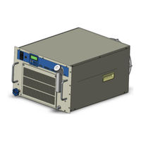
SMC Networks HRR010-A-20 Series Operation Manual (166 pages)
Thermo-chiller
Brand:
SMC Networks
| Category:
Chiller
| Size: 5 MB
Table of Contents
Table of Contents
3
Chapter 1 Safety Instructions
7
Before Using the Product
7
Reading the Manual
7
Hazards
8
Level of Hazards
8
Definition of "Serious Injury" and "Minor Injury
8
Product Label
9
Safety Measures
10
Safety Instructions for Use
10
Personal Protective Equipment
10
Emergency Measures
11
Waste Disposal
12
Disposal of Refrigerant and Compressor Oil
12
Disposal of Product
12
Material Safety Data Sheet (MSDS)
13
Chapter 2 Name and Function of Parts
15
Model Number of Product
15
Operation Display Panel
22
Chapter 3 Transport and Setting up
23
Transport
23
Installation
24
Environment
24
Location
26
Installation and Maintenance Space
28
Installation
29
Mounting
29
Electrical Wiring
30
Preparation and Wiring of Power Supply Cable
32
Contact Input/Output Communication Wiring
34
Wiring of Run/Stop Signal Input and Remote Signal Input
36
Wiring of Contact Output Signal
37
Communication Wiring
38
RS-232C Communication Wiring
40
Piping
41
Fill of Circulating Fluid
45
Chapter 4 Starting the Product
47
Before Starting
47
Starting and Stopping
48
Operation
48
Operation Restart When Alarm Is Generated
49
Stopping the Product
51
Cautions for Re-Start
51
Adjustment of Bypass Valve
52
Check Items after Starting
52
Chapter 5 Display and Setting of Various Functions
53
List of Functions
53
Function
54
Key Operations
54
List of Parameters
58
Main Menu
58
Alarm Display Menu
58
Notice for Maintenance Menu
58
Monitor Menu
59
Standard Setting Menu
60
Alarm Setting Menu
61
Communication Setting Menu
62
Reset Menu
63
Information Monitor Setting Menu
63
Basic Setting Mode
64
Screen Configuration
64
Main Menu
64
Alarm Display Menu
66
Notice for Maintenance Menu
67
Advanced Setting Mode
69
Switch to Advanced Setting Mode
69
Display Contents of Monitor Menu
69
Display Contents of the Standard Setting Menu
71
Alarm Setting Menu
85
Communication Setting Menu
98
Reset Menu
106
Information Monitor Menu
110
Alarm History Menu
114
Chapter 6 Option
115
Option DM【Electric Conductivity Control Function , DI Water (Pure Water) Piping
115
Option M【DI Water (Pure Water) Piping
116
Option T1【Inverter Pump
116
Option Y【With Feet and no Rack Mounting Bracket
117
Anti-Quake Bracket (Optional Accessories)
118
Option Z
119
Option Z1
119
Chapter 7 Alarm Notification and Troubleshooting
121
Alarm Notification
121
Alarm Buzzer Stop
123
Trouble Shooting
124
Alarm Contents, Causes, and Troubleshooting
124
Other Errors
126
Chapter 8 Control, Inspection, Exchange and Cleaning
127
Quality Control of Circulating Fluid and Facility Water
127
Inspection, Exchange, Cleaning
128
Daily Check
128
Monthly Check
130
Inspection Every 3 Months
131
Stop for a Long Time
134
Discharge of the Circulating Fluid
134
Discharge of the Facility Water (Water-Cooled Type)
137
Replacement of Consumables
139
Replacing Particle Filters
139
Replacing the DI Filter (Option DM)
139
Electrical Schematic Diagram
142
Chapter 9 Documents
147
Specifications
147
Refrigerant with GWP Reference
151
Communication Specification
151
Outline Dimensions
152
Flow Chart
154
Cooling Capacity
155
Heating Capacity
157
Hrr010-A-10
159
Pump Capacity
159
Hrr010-A/W-10-T1
159
Required Facility Water Flow (for Water-Cooled Type)
160
Types of Hazard Labels
161
Locations of Hazard Labels
161
Daily Check
162
Chapter 10 Product Warranty
163
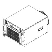
SMC Networks HRR010-A-20 Series Operation Manual (60 pages)
Communication function
Brand:
SMC Networks
| Category:
Chiller
| Size: 1 MB
Table of Contents
Table of Contents
3
Chapter 1 Read before Using
5
Communication Mode and Operation Method
5
Communication Port
7
Key Operations
8
Parameters
12
Chapter 2 Contact Input/Output Communication
13
Precautions for Communication
13
Precautions Wiring Communication
13
Precautions after Wiring and before Communication
13
Communication Specification
14
Connection Explanation
14
Setting and Checking
15
Contact Input Signal 1
17
Run/Stop・Run・Stop・External Switch Signal
25
Signal of the External Switch
26
Contact Output Signal
28
Chapter 3 Serial Communication
31
Precautions Wiring Communication
31
Connected Explanation
31
Communication Specification
32
MODBUS Communication Function
33
Precautions for Communication
33
Precautions after Wiring and before Communication
33
Precautions for Communicating
33
Setting and Checking
34
Setting and Checking Items
34
Setting and Checking
35
Communication Sequence
37
Message Configuration
38
Message Frame
38
Function Codes
39
Checksum Calculation Method
40
Lrc(Ascii)
40
Crc(Rtu)
40
Explanation of Function Codes
42
Function Code:04 Reading Multiple Registers
42
Function Code:06 Writing Registers
43
Function Code:16 Writing Multiple Registers
44
Function Code:23 Reading/Writing Multiple Registers
45
Negative Response
46
Register Map
48
Circulating Fluid Discharge Temperature
49
Circulating Fluid Flow Rate
49
Circulating Fluid Discharge Pressur
49
Electric Conductivity of the Circulating Fluid
49
Status Flag
49
Alarm Flag
50
Data Instruction Information
51
Data Display
51
Circulating Fluid Set Temperature
51
Operation Start Command
51
Serial Remote Instruction
52
Data Instruction
52
Chapter 4 Communication Alarm Function
55
Communication Alarm Occurs
55
Communication Alarm Reset
56
Setting and Checking Items
56
Setting and Checking
57
Advertisement
Advertisement
Related Products
SMC Networks HRR010-A-10 Series
SMC Networks HRR010-W-10 Series
SMC Networks HRR010-W-20 Series
SMC Networks HRR010-A-20-U
SMC Networks HRR010-A-20-DMT1UYZ
SMC Networks HRR010-W-20-U
SMC Networks HRR010-W-20-DMT1UYZ
SMC Networks HRR010
SMC Networks HRR012-W*-20 Series
SMC Networks HRR018
SMC Networks Categories
Switch
Control Unit
Controller
Industrial Equipment
Network Router
More SMC Networks Manuals
Login
Sign In
OR
Sign in with Facebook
Sign in with Google
Upload manual
Upload from disk
Upload from URL