Sign In
Upload
Manuals
Brands
SKF Manuals
Control Unit
SMBM-V42
SKF SMBM-V42 Control Unit Manuals
Manuals and User Guides for SKF SMBM-V42 Control Unit. We have
1
SKF SMBM-V42 Control Unit manual available for free PDF download: Assembly Instructions Manual
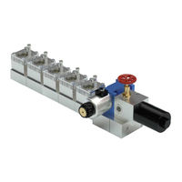
SKF SMBM-V42 Assembly Instructions Manual (100 pages)
Flow limiters
Brand:
SKF
| Category:
Control Unit
| Size: 4 MB
Table of Contents
EC Declaration of Incorporation Acc. to Machinery Directive 2006/42/EC, Appendix II Part 1 B
2
Appendix II Part 1 B
3
Masthead
3
Table of Contents
4
Explanation of Symbols and Signs
8
1 Safety Instructions
10
General Safety Instructions
10
General Behavior When Handling the Product
10
Intended Use
11
Foreseeable Misuse
11
Painting Plastic Components
12
Modifications to the Product
12
Prohibition of Certain Activities
12
Inspections Prior to Delivery
12
Referenced Documents
12
Notes on the Type Plate
13
Note on CE Marking
13
Persons Authorized to Use the Product
14
Operator
14
Qualified Mechanic
14
Qualified Electrician
14
Instruction of Outside Fitters
14
Provision of Personal Protective Gear
14
Operation
14
Emergency Shutdown
14
Transport, Assembly, Maintenance, Malfunction, Repair, Shutdown, Disposal
15
First Start-Up, Daily Start-Up
16
Cleaning
16
Residual Risks
17
2 Lubricants
18
General Information
18
Selection of Lubricants
18
Material Compatibility
19
Aging of Lubricants
19
3 Overview, Functional Description
20
Series SMBM-X (Single Flow) Flow Limiter Versions
20
Series SMBM-V (Dual Flow) Flow Limiter Versions
22
Type Designation of Flow Limiters of Series SMBM
24
Ordering a Complete Flow Limiter Assembly
26
Order Form for a Complete Flow Limiter Assembly
26
Application
27
Functional Description of a Flow Limiter of Series SMBM
28
Example of a Circulating-Oil Lubrication System with Flow Limiter of Series SMBM-X
31
Example of a Circulating-Oil Lubrication System with Flow Limiters of Series SMBM-V
32
4 Technical Data
34
General Technical Data SMBM
34
Piston Detector 24-1884-2785
35
Signal Transmitter 24-1072-2124, Without Cable Box
36
Pulse Generator 2340-00000030 for Gear-Type Flow Indicator
37
Electrical Changeover Valve 24-1254-2486 for Separation of Starting and Main Oil Flow
38
Oil Filter 24-0651-3041
38
Plug-In Nozzle Table SMBM-X
39
Plug-In Nozzle Table SMBM-V
40
Calculation of the Resulting Oil Volumetric Flow
41
Diagram for Determination of the Nozzle Index
41
Diagram for Determination of the Correction Factor for the Volumetric Flow of the Oil
42
Example
43
5 Delivery, Returns, Storage
44
Delivery
44
Return Shipment
44
Storage
44
6 Assembly
45
General Information
45
Minimum Mounting Dimensions
46
Assembly Drawing SMBM-X
47
Assembly Drawing SMBM-X00 Without
47
Gear-Type Flow Indicator, Without Signal Transmitter
47
Assembly Drawing SMBM-X31 with Piston Detector
47
Assembly Drawing SMBM-X21/X22 with Signal Transmitter
48
Assembly Drawing SMBM-X01/X02/ X03 with Gear-Type Flow Indicator
48
Assembly Drawing SMBM-X11/X12/X13 with Gear-Type Flow Indicator and Pulse Generator
49
Assembly Drawing SMBM-X41/X42/X43
49
With Gear-Type Flow Indicator and Signal Transmitter
49
Assembly Drawing SMBM-X61/X62/X63 Flow Limiter with Gear-Type Flow Indicator and Piston Detector
50
Filter Unit for Flow Limiter SMBM-X
50
Base Plates for Flow Limiter SMBM-X
51
Assembly Drawing SMBM-V
53
Assembly Drawing SMBM-V00 Without
53
Gear-Type Flow Indicator, Without Signal Transmitter
53
Assembly Drawing SMBM-V31 with Piston Detector
53
Assembly Drawing SMBM-V21/X22 with Signal Transmitter
54
Assembly Drawing SMBM-V01/V02/V03 with Gear-Type Flow Indicator, Pulse Generator
54
Assembly Drawing SMBM-V11/V12/V13 with Gear-Type Flow Indicator, Pulse Generator
55
Assembly Drawing SMBM-V41/V42/V43
55
SMBM-V51/V52/V53 Flow Limiter with Gear-Type Flow Indicator and Signal Transmitter
55
Assembly Drawing SMBM-V61/V62/V63 Flow Limiter with Gear-Type Flow Indicator and Piston Detector
56
Filter Unit for Flow Limiter SMBM-V
56
Changeover Valve for Flow Limiter SMBM-V
57
Base Plates for Flow Limiter SMBM-V
58
Assembling the Flow Limiters SMBM
60
Mechanical Connection Options SMBM
62
Electrical Connection of Piston Detector 24-1884-2785
63
Electrical Connection of Pulse Generator 2340-00000030
64
Electrical Connection of Signal Transmitter 24-1072-2124
65
Electrical Connection of Changeover Valve 24-1254-2486
67
Lubrication Line Connection
68
7 First Start-Up
69
Inspections before First Start-Up
69
Inspections During First Start-Up
69
8 Operation
70
Temporary Shutdown
70
Permanent Shutdown and Disposal
70
Disposing of Dismantled Parts
70
9 Cleaning
71
Cleaning Agents
71
Exterior Cleaning
71
Interior Cleaning
71
Cleaning of the Pulse Generator
71
10 Maintenance
72
Maintenance for Flow Limiters
72
Maintenance Schedule
72
Changing the Plug-In Nozzle SMBM
74
Changing the Plug-In Nozzle SMBM-X
74
Changing the Plug-In Nozzle SMBM-V
76
New Mounting or Replacement of a Flow Limiter Module While Retaining the Base Plate Module
78
New Mounting with Existing Dummy Module or Replacement of an SMBM-X Module
78
New Mounting with Existing Dummy Module or Replacement of an SMBM-V Module
80
Expansion of an Existing Flow Limiter Assembly to Include an SMBM Module
82
11 Malfunctions, Causes, and Remedies
86
Malfunctions at the Flow Limiter
86
System Malfunctions with Effects on the Flow Limiter
87
12 Repairs
88
Replacement of Signal Transmitter 24-1072-2124
89
Mounting or Replacement of the Pulse Generator 2340-00000030
90
Subsequent Mounting
90
Pulse Generator Replacement
90
Run a Function Check
91
13 Shutdown, Disposal
92
Temporary Shutdown
92
Permanent Shutdown, Disassembly
92
Disposal
92
14 Spare Parts
93
15 Accessories
97
Fitting Tool for Check Valve 24-2104-2049
97
Cable Boxes
97
Advertisement
Advertisement
Related Products
SKF SMBM-V41
SKF SMBM-V43
SKF SMBM-V21
SKF SMBM-V03
SKF SMBM-V11
SKF SMBM-V61
SKF SMBM-V52
SKF SMBM-V53
SKF SMBM-V13
SKF SMBM-V12
SKF Categories
Water Pump
Lubrication systems
Measuring Instruments
Tools
Industrial Equipment
More SKF Manuals
Login
Sign In
OR
Sign in with Facebook
Sign in with Google
Upload manual
Upload from disk
Upload from URL