Sign In
Upload
Manuals
Brands
Sierra Wireless Manuals
Modem
AirLink FXT009
Sierra Wireless AirLink FXT009 Manuals
Manuals and User Guides for Sierra Wireless AirLink FXT009. We have
1
Sierra Wireless AirLink FXT009 manual available for free PDF download: User Manual
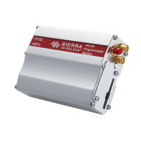
Sierra Wireless AirLink FXT009 User Manual (114 pages)
AirLink FX Series
Brand:
Sierra Wireless
| Category:
Modem
| Size: 3 MB
Table of Contents
Important Notice
2
Safety and Hazards
2
Contact Information
3
Document History
4
Table of Contents
6
1 Overview
15
FX Series Product Comparison
15
Table 1. FXT009 and FX100 Feature Comparison
15
Overall Dimensions
16
Figure 1. FX Series Modem
16
Table 2. FX Series Physical Dimensions
16
FX Series Variants and Bundles
17
Connections
17
Interfaces
17
External Interfaces
17
Table 3. FX Series Variants
17
Internal X-Card Interface
18
Environmental Compliance
18
Rohs Directive Compliant
18
Disposing of the Product
18
2 Features and Services
19
Table 4. FX Series Basic Features
19
Supported Bands
20
X-Card Interface
20
Protection
21
Power Supply
21
Electrostatic Discharge
21
Main Serial Link
21
3 Functional Specifications
22
Functional Architecture
22
Figure 2. Functional Architecture
22
RF Functionalities
23
Operating System
23
Figure 3. FX Series RF Architecture
23
Table 5. FX Series Variants with Corresponding Supported Bands
23
4 Technical Specifications
24
Power Supply
24
Table 6. Power Supply Electrical Characteristics
24
Mechanical Specifications
25
Figure 4. FXT009 Mechanical Drawing
25
Figure 5. FX100 Mechanical Drawing (1 of 2)
26
Figure 6. FX100 Mechanical Drawing (2 of 2)
27
5 Interfaces
28
Front Interface
28
Power Supply Connector
28
Figure 7. FX Series Front Interface
28
Figure 8. Power Supply Connector
28
General Purpose Input/Output
29
Table 7. Power Supply Connector Pin Description
29
Table 8. GPIO Pin Description
29
Figure 12. Equivalent Circuit of
30
Figure 13. Equivalent Circuit of
30
Figure 14. Equivalent Circuit of
30
Table 9. GPIO Pin Operating Conditions When Vref Is at 2.8V
30
Table 10. GPIO Pin Operating Conditions When Vref > 2.8V
31
ON/OFF Pin
33
Table 11. ON/OFF Pin Operation
33
Table 12. ON/OFF Pin Description
33
Serial Interface
34
Figure 17. 15-Pin Serial Connector
34
Table 13. Serial Connector Pin Description
34
Figure 18. RS232 Serial Link Signals
35
RS232 Implementation
35
RS232 Serial Link Connection
35
Figure 19. V24 Serial Link Implementation for a 5-Wire UART
36
Figure 20. V24 Serial Link Implementation for a 4-Wire UART
36
Autobauding Mode
37
Figure 21. V24 Serial Link Implementation for a 2-Wire UART
37
Serial Port Auto Shut down Feature
37
Audio Lines Connection
38
Table 14. Microphone Pin Description for FXT009
38
Table 15. Microphone Pin Description for FX100
38
Table 16. Equivalent Circuits of CMIC
38
Table 17. Electrical Characteristics of CMIC for FXT009
39
Table 18. Electrical Characteristics of CMIC for FX100
39
Figure 22. Equivalent Circuit of CSPK
40
Table 19. Recommended Microphone Characteristics
40
Table 20. Speaker Outputs Pin Description for FXT009
40
Table 21. Speaker Outputs Pin Description for FX100
40
Table 22. Electrical Characteristics of CSPK for FXT009
41
Table 23. Electrical Characteristics of CSPK for FX100
41
Table 24. Recommended Speaker Characteristics
41
USB Interface
42
Figure 23. Mini-B USB Connector
42
Table 25. Mini-B USB Pin Description
42
Table 26. USB Electrical Characteristics for FXT009
42
Table 27. USB Electrical Characteristics for FX100
42
Back Interface
43
SIM Interface
43
Figure 24. FX Series Back Interface
43
SIM Socket Pin Description
44
RF Interface
44
Figure 25. Main RF Connector
44
Figure 26. Secondary RF Connector for FX100
44
Table 28. SIM Socket Pin Description
44
Table 29. Available RF Interface
44
Figure 27. GPS RF Connector for FX100
45
RF Performances
45
Table 30. Main Receiver Parameters for FXT009
45
Table 31. Main Transmitter Parameters for FXT009
45
Table 32. Main Receiver Parameters for FX100
45
Antenna Specifications
46
Table 33. Main Transmitter Parameters for FX100
46
Table 34. Antenna Specifications for FXT009 and FX100
46
GPS Specifications for FX100
47
Table 35. GPS Antenna Specifications for FX100
47
6 Signals and Indicators
49
Alarm Mode
49
BOOT Signal Connection (FXT009 Only)
49
RESET Signal Connection
49
Table 36. Alarm Mode (Low Power Mode)
49
Table 37. FX Series Reset Status
50
Table 38. Reset Electrical Characteristics for FXT009
50
Table 39. Reset Electrical Characteristics for FX100
50
Table 40. Reset Operating Conditions
50
Reset Sequence
51
LED Status Indicator
51
Figure 28. Reset Sequence Diagram
51
Table 41. FX Series LED Status
51
Real Time Clock (RTC)
52
Table 42. Real Time Clock Specifications
52
7 X-Card
53
X-Card Compartment
53
Back Plate Screws
53
50-Pin X-Card Connector
53
Figure 29. FX Series X-Card Compartment
53
Figure 30. 50-Pin X-Card Connector
53
Table 43. 50-Pin X-Card Connector Description
53
X-Card Physical Description
54
Figure 31. X-Card Size
54
X-Card Design Suggestion
55
Figure 32. Suggested X-Card Dimension
55
Fxte02
56
FXTE02 Ethernet X-Card Installation
56
Figure 33. FXTE02 Ethernet X-Card Installation on the FX Series
56
Table 44. Basic Features of FXTE02 Ethernet X-Card
56
Board Architecture
57
Figure 34. FXTE02 Ethernet X-Card Architecture
57
Figure 35. FXTE02 X-Card and an RJ-45 Interface Cable
57
Figure 36. 10-Pin Interface Socket
57
Mechanical Characteristics
58
Power Supply
58
Extra Current Consumption from the DC-IN Source
58
Table 45. 10-Pin Interface Socket Description
58
Table 46. Mechanical Characteristics
58
Table 47. Electrical Characteristics
58
Table 48. Extra Current Consumption from DC-IN Source (Typical)
58
X-Card Removal
59
Figure 37. X-Card Removal Procedure
59
8 Using the Fx Series
60
Mounting the FX Series
60
Figure 38. FX Series Holding Bridles
60
Figure 39. Mounting the FX Series
60
Getting Started
61
Inserting the SIM Card
63
Extracting the SIM Card
64
Using the FX Series with an X-Card
65
Operational Status
65
9 Communicating with the Fx Series
66
Communications Testing
66
Table 49. Basic at Commands to Use with the FX Series
66
Verifying the Received Signal Strength
67
Verifying the Network Registration
67
Checking the Band Selection
67
Table 50. <Rssi> Value Description
67
Table 51. AT+CREG? Main Reponses
67
Table 52. AT+WMBS? Main Reponses
67
Switching Bands
68
Table 53. AT+WUBS? Main Reponses
68
Table 54. AT+WWSM? Main Reponses
68
Table 55. AT+WMBS Band Selection
68
Table 56. AT+WUBS Band Selection
69
Table 57. AT+WWSM Cellular Network Setting
69
Checking the PIN Code Status
70
Echo Function
70
Enabling/Disabling the Flash LED
70
Firmware Upgrade Procedure
70
Table 58. AT+CPIN Main Responses
70
Main at Commands for the FX Series
71
Table 59. Main at Commands Used for the FX Series
71
10 Troubleshooting the Fx Series
72
No Communications with the FX Series through the Serial Link
72
Receiving "ERROR
72
Table 60. no Communications with the FX Series through the Serial Link
72
Receiving "NO CARRIER
73
Table 61. Receiving a "No Carrier" Message
73
Table 62. Extended Error Codes
74
11 Power Consumption
75
Various Operating Modes
75
Table 63. Initial Power Consumption (Typical)
75
Table 64. FX Series Operating Modes
75
Working Mode Features
76
Table 65. FX Series Operating Modes Feature Availability
76
Connected Mode Power Consumption
77
Table 66. Power Consumption of FXT009 in Connected Mode with Serial Port on and Flash LED
77
Table 67. Power Consumption of FX100 in Connected Mode with Serial Port OFF, Flash LED off
78
Non-Connected Mode Power Consumption
80
Table 68. Power Consumption of FXT009 in Non-Connected Mode (Typical Values)
80
Consumption Measurement Procedure
81
Hardware Configuration
81
Equipment
81
Table 69. Power Consumption of FX100 in Non-Connected Mode with UART ON, FLASH LED off and USB off (Typical Values)
81
SIM Cards Used
82
Software Configuration
82
Figure 40. Typical Hardware Configuration for Power Consumption Measurement
82
Table 70. List of Recommended Equipments
82
Equipment Configuration
83
FX Series Configuration
83
Table 71. Operating Mode Information
83
12 Recommendations When Using the Fx Series on Trucks
86
Recommended Power Supply Connection on Trucks
86
Figure 41. Recommended Power Supply Connection on Trucks
86
Technical Constraints on Trucks
87
Figure 42. Example of an Electrical Connection that May Damage the FX Series
87
13 Fx Series Accessories
88
Standard Accessories
88
Additional Optional Accessories
88
Table 72. 6-Wire Cable Accessory Color Coding
88
Component Recommendations
89
Table 73. List of Recommended Accessories
89
14 Reliability Compliance and Recommended Standards
90
Reliability Compliance
90
Applicable Standards Listing
90
Table 74. Standards Conformity for the FX Series
90
Table 75. Applicable Standards and Requirements for the FX Series
90
Environmental Specifications
91
Table 76. Operating Class Temperature Range
91
Function Status Classification
92
Reliability Prediction Model
92
Life Stress Test
92
Table 77. ISO Failure Mode Severity Classification
92
Table 78. Life Stress Test
92
Environmental Resistance Stress Test
93
Corrosive Resistance Stress Test
93
Table 79. Environmental Resistance Stress Test
93
Table 80. Corrosive Resistance Stress Test
93
Thermal Resistance Cycle Stress Test
94
Mechanical Resistance Stress Tests
94
Table 81. Thermal Resistance Cycle Stress Test
94
Table 82. Mechanical Resistance Stress Tests
94
Handling Resistance Stress Tests
96
Table 83. Handling Resistance Stress Tests
96
15 Certification Compliance and Recommended Standards
97
Certification Compliance
97
Table 84. Standards Conformity Forfxt009
97
Table 85. Standards Conformity for FX100
97
UL Listed
98
Applicable Standards Listing
98
Table 86. Applicable Standards and Requirements for FXT009
98
Table 87. Applicable Standards and Requirements for FX100
99
16 Safety Recommendations
100
General Safety
100
Vehicle Safety
101
Care and Maintenance
101
Your Responsibility
101
17 Reference Documents
102
Firmware Documentation
102
X-Card Documentation
102
Firmware Upgrade Documentation
102
18 List of Abbreviations
103
19 Packaging
106
Contents
106
Accessories Description
106
GSM Antenna
106
Table 88. Configuration Availability for the FX Series
106
Table 89. GSM Antenna Description
106
GPS Antenna
107
Serial Data Cable
107
Table 90. GPS Antenna Description
107
Table 91. Serial Data Cable Description
107
USB Cable
108
6-Wire Cable Accessory Used with the FX Series
108
Package
108
Two Holding Bridles
108
Figure 43. Holding Bridle Description
108
Table 92. 6-Wire Cable Accessory Description
108
Table 93. Packaging Description
108
Power Supply Used with the FX Series
109
Table 94. Power Supply Description
109
20 Product Labeling
110
Figure 44. FX Series Product Label
110
21 Safety Recommendations (for Information Only)
111
RF Safety
111
General
111
Exposure to RF Energy
111
Efficient Terminal Operation
111
Antenna Care and Replacement
112
General Safety
112
Driving
112
Electronic Devices
112
Vehicle Electronic Equipment
112
Medical Electronic Equipment
112
Aircraft
113
Children
113
Blasting Areas
113
Potentially Explosive Atmospheres
113
Advertisement
Advertisement
Related Products
Sierra Wireless AirLink FX100
Sierra Wireless AirLink 595W
Sierra Wireless AirLink MP595
Sierra Wireless AirLink MP
Sierra Wireless AIRLINK MP595W
Sierra Wireless AirLink MP890
Sierra Wireless AirLink MP895
Sierra Wireless AirLink GL8200
Sierra Wireless Airlink GX450
Sierra Wireless AirLink Raven 1x
Sierra Wireless Categories
Modem
Gateway
Wireless Router
Control Unit
Network Card
More Sierra Wireless Manuals
Login
Sign In
OR
Sign in with Facebook
Sign in with Google
Upload manual
Upload from disk
Upload from URL