Sign In
Upload
Manuals
Brands
Siemens Manuals
Control Unit
TM SIWAREX WP351 HF
Siemens TM SIWAREX WP351 HF Manuals
Manuals and User Guides for Siemens TM SIWAREX WP351 HF. We have
1
Siemens TM SIWAREX WP351 HF manual available for free PDF download: Operating Instructions Manual
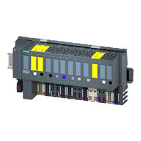
Siemens TM SIWAREX WP351 HF Operating Instructions Manual (166 pages)
Technology module
Brand:
Siemens
| Category:
Control Unit
| Size: 4.7 MB
Table of Contents
Table of Contents
3
1 Introduction
11
Purpose of this Document
11
Use in Hazardous Area
11
Security Information
12
Open Source Software
13
2 Product Overview
15
View
15
Properties
16
Version Dependencies of the Functions
16
3 Installing
17
Basic Safety Notes
17
Atex/Iecx Special Conditions for Use
17
Mounting on the SIMATIC ET 200SP
18
EMC-Compliant Installation
19
Introduction
19
Possible Effects of Interference
19
Coupling Mechanisms
19
Five Basic Rules for Securing EMC
20
4 Connecting
23
Basic Safety Notes
23
Atex/Iecx Special Conditions for Use
23
Connection to Electronic Weighing System
24
Connection of Analog Load Cells
27
Connecting SIWAREX JB to the Electronic Weighing System and Load Cell
28
Wiring Diagrams
28
Load Cells with Four-Wire System
28
Load Cells with Six-Wire System
30
Connecting Cables to SIWAREX JB
31
5 Commissioning
33
Calibration with Calibration Weights
33
Automatic Calibration
35
6 Parameter Assignment/Addressing
37
Introduction
37
TIA Portal User Program
38
Commissioning the Electronic Weighing System with TIA Portal
38
Calling the Function Block (FB)
41
Executing Commands
44
Cyclic Data Exchange Via "Cycliciodata
46
Reading/Writing Data Records
48
Design of Hardware Configuration
49
Web Server
50
Calling the Web Server
50
Reading/Writing Data Records
51
Operating Modes
53
Weighing Steps
53
NAWI - Non Automatic Weighing Instrument
53
NAWI - Non-Automatic Weighing Instrument - Filling
53
NAWI - Non-Automatic Weighing Instrument - Emptying
54
GFI - Gravimetric Filling Instrument
55
CWI - Catchweighing Instrument / CW - Automatic Check Weigher
55
CWI - Catchweighing Instrument/ CW - Automatic Check Weigher - Filling
55
CWI - Catchweighing Instrument/ CW - Automatic Check Weigher - Emptying
56
DTI Discontinuous Totalizing Automatic Weighing Instrument
57
CW - Automatic Check Weigher
58
DR03 Calibration Parameters
58
Overview
58
Scale Name [Scalename]
59
Weight Unit [Weightunit]
59
Gross Indicator [Grossindicator]
59
Restriction Code [Restrictioncode]
60
Set Number of Weighing Ranges [Numberofweighingranges]
60
Multi Range / Multi Interval Scale [Multirangemultiintervalscale]
61
Calibration Weights 0, 1, 2, 3, 4 [Calibrationweight] and Calibration Digits [Calibrationdigit]
62
Scale Interval for Weighing Range 1, 2, 3 [Scaleintervalweighingrange]
63
Initial Zero-Setting [Initialzerosetting]
63
Initial Zero-Setting if Tared [Initialzerosettingiftared]
63
Automatic Zero Tracking Device [Automaticzerotracking]
63
Tare Device [Subtractiveadditivetare]
63
Enable Weight Simulation [Weightsimulationenabled]
64
Automatic Zero-Setting Device [Automaticzerosetting]
64
Weighing Range Data in Securedisplay [Weighingrangedatainsecuredisplay]
65
Automatic Zero Tracking in Dosing Cycle [Automaticzerotrackingincycle]
65
Maximum Tare Weight (% of Max.) [Maxtareweight]
65
Initial Zero-Setting Device Limit Negative (% of Max.) [Initialzerosettinglimitnegative]
65
Initial Zero-Setting Device Limit Positive (% of Max.) [Initialzerosettinglimitpositive]
65
Semi-Automatic Zero-Setting Device Limit Negative (% of Max.) [Semiautomaticzerosettinglimitnegative]
66
Semi-Automatic Zero-Setting Device Limit Positive (% of Max.) [Semiautomaticzerosettinglimitpositive]
66
Stability Monitoring
66
Digital Signal Filters
68
Operating Mode [Scaleoperatingmode]
69
Totalization Scale Interval Dt [Totalizationscaleintervaldt]
69
Minimum Totalized Load [Minimumtotalizedload]
69
Securedisplay Interface [Legaldisplayinterface]
69
Securedisplay Version [Securedisplayversion]
70
Smallest Zoom Factor of Securedisplay (%) [Smallestzoomfactorofsecuredisplay]
70
DR04 Calibration Curve Check
70
DR05 Tare and Zero Memory
70
DR06 Configuration of Limits
71
Reference (Limits 1 and 2) [Limitreference]
71
Limit 3 - Empty [Emptylimit]
71
Switch-On Delay Limit 3 (Empty) (S) [Delaytimeforemptylimit]
72
DR07 Interface Parameters
72
Assignment DI.0, DI.1, DI.2, CI [Functiondi0 to Functiondi2] [Functionci]
72
Filtering DI.0, DI.1, DI.2 and CI
73
Assignment DQ.0, DQ.1, DQ.2
73
Reaction to CPU Stop / Failure [Behaviouroncpustoporfailure]
73
Monitoring of Digital Outputs [Monitoringofdq]
74
Reaction of Digital Outputs to a CPU Stop / Failure [Behaviourofdqoncpustoporfailure]
74
Behavior of Digital Outputs on Error [Behaviourofdqonerror]
74
Substitute Value for DQ.0 to DQ.3 on Error
74
Trace Rate [Tracerate]
75
Subnet Mask, IP Address, Gateway, Device Name
75
Activate Modbus Communication [Activatemodbusconnection1] [Activatemodbusconnection2]
75
Modbus TCP Unit Identifier, Port, SWAP Options
76
Byte/Word Swap Options [Byteswap16Bit] [Byteswap32Bit] [Wordswap32Bit]
76
RS485 Protocol
76
I/O Process Values 1 to 4 [Ioprocessvalue1 to Ioprocessvalue4]
76
I/O Process Values 5 to 8 [Ioprocessvalue5 to Ioprocessvalue8]
77
Event Hardware Interrupts 4 to 8 [Hardwareinterrupt4 to Hardwareinterrupt8]
78
Source for Weight Simulation [Simulationsource]
78
DR09 Read out Module Information
78
DR10 Load Cell Parameters
78
Load Cell Type [Loadcelltype]
78
Connection Technology [Foursixwiresensor]
79
Load Cell Manufacturer [Loadcellmanufacturer] and Load Cell Order Number [Loadcellordernumber]
79
Of Mechanical Support Points [Numberofsupportpoints]
79
Averaged Load Cell Characteristic (MV/V) [Averagedcharacteristicvalue]
79
Nominal Load of One Single Load Cell [Nominalloadofsingleloadcell]
79
Power Line Frequency [Powerlinefrequency]
80
Using a Power Line Filter [Powerlinefilteractivated]
80
External / Internal Sensor Supply [Internalexternaladcsupply]
80
Impedance
80
DR15 Preset Tare
80
DR16 Configuration of Weight Simulation
81
Simulate Weight
81
Simulating Dosing
82
Material Flow, Delay Time and Opening/Closing Time
83
DR18 Digital Output and Transition Control
84
Controlling Digital Outputs
84
Enabling Transitions
85
DR20 Configuration of Set Point [Setpoint]
86
DR21 Configuration of Total Set Point [Totalsetpoint]
86
DR21 Configuration of Total Set Point in DTI
86
DR21 Configuration of Total Set Point GFI
87
DR22 Tolerance Parameters
88
Overview
88
Parameter Relation [Parameterrelation]
88
Tolerance Limit TH2 (Weight Unit) [Tolerancelimitth2]
88
Tolerance Limit TH1 (Weight Unit) [Tolerancelimitth1]
89
Tolerance Limit TL1 (Weight Unit) [Tolerancelimittl1]
89
Tolerance Limit TL2 (Weight Unit) [Tolerancelimittl2]
89
Behavior in Case of TH1 Error [Behaviorth1Violated]
89
Behavior in Case of TL1 Error [Behaviortl1Violated]
89
Pulse Duration for Pulse Post Dosing (S) [Pulseduration]
90
Number of Unchecked Weighing Cycles [Cycleswithoutcheck]
90
Capture of Weighings into Statistics [Statisticsdata]
91
DR23 Material Parameters
91
Parameter Relation [Parameterrelation]
91
Fine Weight [Fineweight]
91
Trailing Weight Fine [Trailingweightfine]
92
Coarse Weight [Coarseweight]
93
Trailing Weight Coarse [Trailingweightcoarse]
93
Trailing Weight Extra Coarse [Trailingweightxcoarse]
93
Blocking Time Extra Coarse (S) [Blockingtimexcoarse]
93
Blocking Time Coarse Signal (S) [Blockingtimecoarse]
94
Blocking Time Fine Signal (S) [Blockingtimefine]
94
Blocking Time Discharging (S) [Blockingtimedischarge]
94
External Triggered Blocking Time (S) [Externalblockingtime]
94
Shut-Off Correction Weight [Shutoffcorrectionweight]
94
Minimum Material Flow (Weight/S) [Minimummaterialflowrate]
95
DR24 Controller Parameters
95
Parameter Relation [Parameterrelation]
95
Type of Controller [Controllertype]
95
Control Factor of Proportional Controller (%) [Controlfactorpcontroller]
96
Control Factor of Fine Time Controller (%) [Controlfactortcontroller]
96
Max. Control Access of Proportional Controller [Maximumcontrollaccesspcontroller]
96
Proportional Controller Deadband - Upper Limit [Deadbandpcontrollerplus]
96
Proportional Controller Deadband - Lower Limit [Deadbandpcontrollerminus]
97
Controller Behavior in Case of Exceeding Max. Control Access [Controllererrorbehavior]
97
Intervention of Fine Time Controller [Interventiontcontroller]
97
Set Point Fine Time Controller (S) [Setpointtcontroller]
97
Adopt Corrected Fine-/Trailing Values to DR23 Automatically [Adoptcorrectedvalues]
98
Max. Control Access of Fine Time Controller [Maximumcontrollaccesstcontroller]
98
DR25 Dosing System Parameters
98
Maximum Single Set Point [Maximumsinglesetpoint]
98
Minimum Automatic Tare Weight (% of Max.) [Minimumautomatictareweight]
98
Maximum Automatic Tare Weight (% of Max.) [Maximumautomatictareweight]
98
Maximum Weighing Time (S) [Maximumdosingtime]
99
Weighing Start Options [Startoptions]
99
Cycle Time for Automatic Zero Setting (S) [Cycletimeautomaticzerosetting]
99
Number of Weighings Without Automatic Taring/Zero Setting [Numberofcycleswithoutzerosetting]
99
Check Stop [Checkstopafterstep0 to Checkstopafterstep7]
99
Automatic Discharging [Dischargemode]
100
Discharge Time (S) [Dischargetime]
101
Maximum Discharge Time (S) [Dischargemonitoringtime]
101
Discharge Overlapping Time [Dischargeoverlappingtime]
101
Of Optimized Loadings (OIML R-107) [Numberofoptimizedloadings]
101
Dosing Signals
102
Delete Tare in Weighing Step 0 [Deletetarestep0]
102
DR28 Configuration of Additional String for Protocols
102
Log with Additional String [Addadditionaltext]
102
Log Single Loadings (OIML R-107) [Logsingleloadings]
103
DR29 Configuration of Technology Messages
103
DR30 Read out Process State
103
Overview
103
Digits Unfiltered (Linearized) [Unfiltereddigitsnotlin]
104
Digits Filtered by F1 [Filtereddigits1]
104
Digits Filtered by F2 [Filtereddigits2]
104
Digits Filtered by F3 [Filtereddigits3]
104
Status DI.0, DI.1, DI.2 and CI.0 [Statusdi0] [Statusdi1] [Statusdi2] [Statusci0]
104
Status DQ.0, DQ.1 and DQ.2 [Statusdq0 to Statusdq2]
104
Refresh Counter [Refreshcounter]
105
Current Load Cell Signal Voltage (MV) [Loadcellsignalvoltage]
105
Load Cell Impedance (Ohm) [Loadcellimpedance]
105
Current Load Cell SEN Voltage (V) [Loadcellsensevoltage]
105
Current Fine Weight [Currentfineweight]
105
Current Trailing Weight [Currenttrailingweightfine]
105
Tolerance Limits (Weight Unit) [Tolerancelimitth2] [Tolerancelimitth1] [Tolerancelimittl1] [Tolerancelimittl2]
105
Gross Process Weight 1 [Grossprocessweight1], Net Process Weight 1
106
[Netprocessweight1], Tare Process Weight [Tareprocessweight]
106
Gross Weight [Grossweight], Net Weight [Netweight], Tare Weight [Tareweight]
106
Gross/Net Weight X10 [Netweightx10]
106
Gross Process Weight 2 [Grossprocessweight2], Net Process Weight 2
106
[Netprocessweight2]
106
Last Net Process Weight [Lastnetprocessweight], Last Net Weight [Lastnetweight]
106
Totalizer 1 [Totalizer1] and Totalizer 2 [Totalizer2]
106
Youngest Protocol ID [Youngestlogid]
106
Date & Time
107
Current Dosing Step [Subdosingstep]
107
Number of Dosings in Continuous Mode [Dosingsincontinuousmode]
107
Difference Set Point / Actual Value [Differencesetpointactualvalue]
107
DR32 Read out Error Messages
107
Overview
107
Operating Errors, Technology Messages, Data/Command Errors
107
DR34 Weight Indicator
108
DR38 Advanced Diagnostic Data
108
DR39 Statistical Data
108
DR45 Protocol Request
109
DR46 Read out Protocol Content
109
Overview
109
Oldest Protocol ID [Oldestlogid]
109
Youngest Protocol ID [Latestlogid]
109
Selected Protocol ID, Numerical [Selectedlogid]
109
Protocol String [Log]
110
Checksum, Date, Time
110
DR47 Read out Logbook Content
111
Commands
111
Overview
111
Commands
112
Command Groups of the Electronic Weighing System
118
Communication Via Modbus
118
Introduction
118
Principle of Data Transmission
119
Data Record Concept
119
Command Mailboxes
119
Reading Registers
120
Writing Registers
121
7 Operation Requiring Official Calibration
123
Prepare Calibration of the Scales
123
Checking Parameters Relevant to the Calibration
125
8 Service and Maintenance
127
Disposal
127
9 Interrupts/Diagnostic Messages
129
Message and Error Types
129
Evaluating Errors/Messages Using the Web Server
129
Evaluating Errors/Messages Using the FB
130
Operating Errors
130
Technology Messages
131
Data and Command Errors
133
Add Info [Erroraddinfo] for DR03
137
Add Info [Erroraddinfo] for DR05 and DR06
139
Add Info [Erroraddinfo] for DR07
139
Add Info [Erroraddinfo] for DR10
141
Add Info [Erroraddinfo] for DR20 to DR24
142
Add Info [Erroraddinfo] for DR25 and DR28
143
Diagnostic Messages
144
Error Codes and Corrective Measures
144
Meaning of the Leds
145
Hardware Interrupts
147
10 Technical Data
149
General Information
149
Analog Load Cell Interface Connection
150
Digital Inputs DI
151
Digital Outputs DQ
151
Counter Input CI
152
Interface
152
Ethernet
153
Dimensions and Weights
153
Mechanical Requirements and Data
153
Electrical, EMC and Climatic Requirements
154
Ambient Conditions
157
Certificates and Approvals
157
Product Documentation and Support
159
Product Documentation
159
Technical Support
159
Ordering Data
161
Accessories
161
Index
163
Advertisement
Advertisement
Related Products
Siemens SCALANCE W788C-2
Siemens WF 723 C
Siemens SCALANCE W788C-2 RJ45
Siemens SCALANCE W788C-2 M12
Siemens WF 726
Siemens SIMATIC NET SCALANCE W721-1
Siemens SIMATIC NET SCALANCE W722-1
Siemens SIMATIC NET SCALANCE W761-1
Siemens WFZ56 Series
Siemens WFZ661
Siemens Categories
Industrial Equipment
Controller
Control Unit
Oven
Washer
More Siemens Manuals
Login
Sign In
OR
Sign in with Facebook
Sign in with Google
Upload manual
Upload from disk
Upload from URL