Sign In
Upload
Manuals
Brands
Siemens Manuals
Control Unit
LME76
Siemens LME76 Manuals
Manuals and User Guides for Siemens LME76. We have
1
Siemens LME76 manual available for free PDF download: Basic Documentation
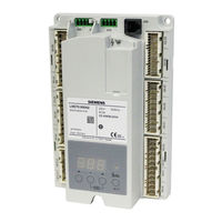
Siemens LME76 Basic Documentation (177 pages)
Burner control
Brand:
Siemens
| Category:
Control Unit
| Size: 3 MB
Table of Contents
Supplementary Documentation
2
Table of Contents
3
Typographical Conventions
9
Safety Notes
9
Qualified Personnel
9
Correct Use
9
Overview
10
System Makeup / Description of Functions
10
Indication and Diagnostics
12
Features
12
Lme75/Lme76
13
PME75/PME76 for 120 V AC Mains Voltage
14
PME75/PME76 for 230 V AC Mains Voltage
16
Display Units / Operating Units and Accessories
18
Lfs1
18
Qra7
19
Qri
19
Ionization Probe
19
Sqn70/Sqn71
20
Sqn72
20
Actuator SQM40
21
Actuator SQM41
22
Actuator SQM5
23
QPL Pressure Switch
24
Dummy Plug for RJ11
24
AGG3 Connector Sets for LME75/LME76
24
AGG9 Connector Sets for LME75/LME76
25
OCI410 Service Tools
26
PC Software ACS410
26
Mounting/Assembly
27
Mounting Notes
27
Standards and Certificates
28
Safety Notes
30
Warning Notes
30
Installation Notes
32
Electrical Connection of the Flame Detectors
33
Disposal Notes
34
Lifetime
35
Wiring
36
Inputs/Outputs
36
Introduction to Wiring
37
Terminals
37
Earthing
38
Protective Earth PE
38
Functional Earth FE
38
Description of the Terminals
39
Terminal X2-03 / X3-04
39
Terminal X2-01 / X2-02 / X6-03
40
Terminal X3-02 / X5-01 / X5-03 / X9-04
41
Terminal X10-05 / X10-06
43
Terminal X4-02 / X7-01 / X7-04
45
Terminal X2-09 / X7-02
46
Terminal X56 / X65 / X66 / X76
47
Assignment of Terminals for Plug AGG9
48
Lme75
48
Lme76
49
Startup
50
Startup Notes
50
Technical Data
52
Lme75/Lme76
52
Terminal Loading: Inputs
53
Terminal Loading: Outputs
54
Cable Lengths
56
Actuators
57
Cross-Sectional Areas
57
RAST5 Connector
57
RAST3.5 Connector
58
Signal Cable AGV50
58
AZL2 / OCI410 BC Interface
58
Dummy Plug for RJ11
58
Environmental Conditions
59
Flame Supervision
60
Ionization Probe with LME75/LME76 at Terminal X10-06
60
QRA7 with LME75 at Terminal X10-05
62
QRI with LME75 at Terminal X10-05
64
LFS1 with LME76 at Terminal X10-05
65
Dimensions
69
Description of Inputs on LME75/LME76
69
Air Pressure Switch Terminal X3-02
70
Pressure Switch-Min Terminal X5-01
71
Pressure Switch-Max, POC/CPI, Valve Proving ON/OFF or Oil Temperature Limiter Terminal X2-02
72
Pressure Switch Valve Proving or Pressure Switch-Max Terminal X9-04
74
Ionization Probe Terminal X10-06
76
QRA7/QRI Terminal X10-05 (LME75 Only)
77
LFS1 Terminal X10-05 (LME76 Only)
79
Flame Safeguard Test
80
Analog Input Load Controller Terminal X65
81
External Load Controller (ON/OFF) Terminal X5-03
83
Safety Loop Terminal X3-04
85
Description of Outputs on LME75/LME76
86
Fan Motor Terminal X2-01
86
Oil Temperature Limiter or PWM Fan Motor Terminal X2-02
87
PWM Fan Motor Control Terminal X76
89
Alarm / Remote Lockout Reset Terminal X2-03
90
Alarm Terminal X2-03 Pin 3
90
Remote Lockout (Reset) Terminal X2-03 Pin 1
90
Actuator Terminal X2-09
91
Connection of Feedback Actuator Position with ASZ in Actuator at Terminal X66
93
Ignition Transformer Terminal X4-02
95
Safety Valve Terminal X6-03
95
Fuel Valve V2A / Pilot Valve PV Terminal X7-01 / X7-04
96
Fuel Valve V1 Terminal X7-02 / X7-04
97
Fuel Valve V2 Terminal X7-01 / X7-02
98
BC Interface Terminal X56
99
Function
100
Preconditions for Startup
100
Undervoltage
100
Controlled Intermittent Operation (Optional)
100
Control Sequence in the Event of Fault
101
Resetting the LME75/LME76
101
Operation, Indication, Diagnostics
102
Operation
102
Operating Display
102
Diagnostics of Cause of Error
103
Multistage or Modulating Operation with Actuator
105
Actuators
107
Function
107
Load Controller Inputs
108
Analog Input Terminal X65
108
Setting the Maximum Running Time of the Actuator (Parameter 259.00 / Parameter 260 Timeout)
108
Multistage/Modulating Mode Via 3-Position Step Input Terminal X5-03
110
Maximum Possible Resolution
110
Modulating Mode Via Analog Input Signal Terminal X65
110
Standardization of Modulation Range
110
Setting the Minimum Power Adjustment (Dead Band) (Parameter 123) in Modulating Mode Via Analog Input Signal Terminal X65
111
Application Limits/Examples
112
Safety Notes for Use of the AZL2
113
Operation Via AZL2
114
Description/Meanings of Displays and Buttons
114
Meaning of Symbols on the Display
115
Special Functions
115
Manual Locking
115
Operation
116
Normal Display
116
Standby Display
116
Startup/Shutdown Display
116
Phase Display
116
List of the Phase Display
117
Operating Position Display
118
Fault Status Messages, Display of Errors and Info
119
Display of Errors (Faults) with Lockout
119
Reset
119
Menu-Driven Operation
120
Assignment of Levels
120
Info Level
121
Display of Info Level
121
Parameter Index
121
Display of Info Values
122
Identification Date
122
Identification Number
122
Burner Identification
123
Number of Startups Resettable
124
Total Number of Startups
125
End of Info Level
126
Service Level
127
Service Level Display
128
Display of Service Values
129
Error History
129
Mains Voltage
129
Intensity of Flame
129
End of Service Level
130
Parameter Level
131
Entering the Password
134
Changing the Heating Engineer's Password
136
Changing the OEM Password
138
Backup
139
Restore
141
Operating Variants of the Parameters
143
Parameters Without Index, with Direct Display
144
Example of Parameter 226 (Preignition Time) on the Parameter Level
144
Parameters Without Index, with no Direct Display
146
Example of Parameter 224 (Specified Time Air Pressure Switch) on the Parameter Level
146
Parameters with Index, with or Without Direct Display
148
Example of Parameter 701: Actual Error on the Service Level
148
Operation Via Internal LED Display
151
Meanings of Displays and Buttons
151
Normal Display
152
Standby Display
152
Startup/Shutdown Display
152
Phase Display
152
List of the Phase Display
153
Operating Position Display
154
Special Functions
154
Manual Locking
154
Fault Status Messages and Display of Errors
155
Display of Errors (Faults) with Lockout
155
Intensity of Flame Ionization
156
Intensity of Flame QRA7/QRI (LME75) or LFS1 (LME76)
157
Reset
157
Display of Preset Output
158
Manual Load Change (Depending on the PME75/PME76 and Respective Parameterization)
159
Actuator Position or Speed of PWM Fan Motor in Modulating Operation with Analog Signal
159
Initial Startup with a New PME75/PME76 or When Replacing the PME75/PME76
162
Manual Backup
164
Error During Backup Process
165
Manual Restore
166
Error During Restore Process
168
Reset
168
Error Code List
169
Unit History
172
Table of Figures
176
Advertisement
Advertisement
Related Products
Siemens LME11 series
Siemens LME21 series
Siemens LME22 series
Siemens LME23 series
Siemens LME44 series
Siemens LME75.000A1
Siemens LME76.000A1
Siemens LME75.000A2
Siemens LME76.000A2
Siemens LMO24 Series
Siemens Categories
Industrial Equipment
Controller
Oven
Control Unit
Washer
More Siemens Manuals
Login
Sign In
OR
Sign in with Facebook
Sign in with Google
Upload manual
Upload from disk
Upload from URL