Sign In
Upload
Manuals
Brands
Shimadzu Manuals
Medical Equipment
MUX-100DJ
Shimadzu MUX-100DJ Manuals
Manuals and User Guides for Shimadzu MUX-100DJ. We have
2
Shimadzu MUX-100DJ manuals available for free PDF download: Installation Manual, Service Manual
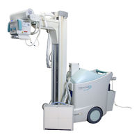
Shimadzu MUX-100DJ Installation Manual (208 pages)
Mobile X-ray System
Brand:
Shimadzu
| Category:
Medical Equipment
| Size: 3 MB
Table of Contents
Table of Contents
3
Chapter 1. Introduction
7
Directions for Using the Unit
8
Document List
13
Chapter 2. Outline
15
Name of each Part of the Unit
16
Conditions for Installation (Using)
20
Conditions for Transportation and Storage
21
Chapter 3. Parations for Installation
24
Tools Required for Installation
24
Unpacking
25
How to Open/Close the Covers
27
Chapter 4. Installation
35
Preinstallation Procedures
37
Installation Procedures
38
Assemble for the CXDI-50G
39
Installation of CXDI Control S/W
43
Setup of CXDI
45
Installation of CXDI Generator Communication S/W
50
Setup of CXDI Generator Communication S/W
53
Check of CXDI Generator Communication S/W
61
Use Permission Setting of External Storage Medium
61
Installation of MLT-M S/W (Optional)
68
Check of MLT-M S/W (Optional)
69
Calibration
71
Selftest
73
Installation of DMW-PS (Optional)
73
Setup of DMW-PS (Optional)
74
Check of DMW-PS Function (Optional)
74
Setup of Annotation
74
Setup of DICOM Storage and Print
74
Acquisition of Image with Phantom
75
Check of REX Value
75
Check of DICOM Storage and Print Function
75
Check of Image
75
Check Table
76
Removement of 50G and Power Box from MUX-100D
77
Packing and Sending MUX-100D and 50G
77
Adjustment of Image Quality
77
Installing the Arm Cover
78
Attaching of a Knob for Locking Collimator Rotation
79
Changing According to the Power Supply
80
Setting of XCONT
81
Checking Performance of each Part
82
Initial Setting
85
Attaching Screw Caps
87
Charging the Battery after Installation
88
Installing an Apron Hanger
88
Assembler Test
88
Chapter 5. Installing the Options
89
Setting DIP Switches on NEXSC Board
90
Installing Remote Controller Option
91
Installing Protective Screen Option
95
Installing Dose Area Meter Option
97
Chapter 6. Specifications
101
Specifications
101
Dimensional Drawing of the Unit
106
X-Ray Reference Axis and Focal Spot Position
107
Exposure Condition
108
Appendix A. NEXSC DIP Switch Settings
111
Table of NEXSC DIP Switch Settings
112
Appendix B. Adjustment Mode
113
How to Get into Adjustment Mode
114
Adjustment Mode List
115
Adjustment of Tube Current
116
Adjustment of the Handle
122
Adjustment of the Battery Voltage Detection Circuit
124
Setting Date and Time
125
Display and Reset of Exposure Counter
127
Display and Reset of Cumulated Mileage
128
Display and Reset of Error Log
130
Display and Reset of Battery Charge Counter
131
Display Running Speed
132
Battery Voltage Drop Check Mode
134
Appendix C. Adjusting Methods
137
C.1 Preperation
137
Adjusting MUX CHARGE-04A Board
139
Adjusting XCONT-2002 Board
140
Adjusting the Battery-Voltage Detection Circuit
143
Checking the X-Ray Exposure
144
Checking Battery Charging
146
Volume Control of a Buzzer
147
Finish
149
Appendix D. Error Message List
151
Error Message List
151
Appendix E. Maintenance and Inspection
155
Expendable Parts List
156
Batteries Replacement
157
CPU Backup Battery Replacement
161
Collimator Lamp Replacement
162
Maintenance of Rotary X-Ray Tube Section
163
Centering the Collimator and X-Ray Focus
168
Adjustment of Collimator Lamp Voltage
172
Cleaning and Disinfections
174
DR System - MUX Communication
176
How to Restration from Recovery CD
191
Appendix F Operation of High-Voltage Cable
201
Spare Parts with High-Voltage Cable
202
Installation Procedure of the High-Voltage Generator Side Plug
203
Installation Procedure of the X-Ray Tube Assembly Side Mini-Plug
204
Appendix G Super-Maintenance Function
205
Super-Maintenance Function
205
Advertisement
Shimadzu MUX-100DJ Service Manual (121 pages)
Brand:
Shimadzu
| Category:
Medical Equipment
| Size: 9 MB
Table of Contents
Table of Contents
2
1 Outline
4
Features
4
Specifications
5
System Drawing
11
Name of each Part ・・・・・・・・・・・・・・・・・・・・・・・・・・・・・・・・・・・・・・・・・・・・・・・・・・・・・・・・・・・・・・・・・・・・・・・・・・・・・・1-10
13
2 Required Tools and Pcb Layout
15
Layout of each PCB
15
Outline of each PCB
17
3 Internal Connection
19
Total Connection Diagram
19
Basic Operation of each Part
22
Power ON/OFF Operation
22
Operation When Power Plug Is Connected
23
Detection of Battery Voltage
23
Charging Circuit
24
Inverter Circuit for Starter and Lamp
25
Main Inverter Unit, Filament Heating Inverter Unit and Starter Circuit
26
Power ON/OFF Circuit for DR System
27
4 Installation and Maintenance/Inspection
28
Environmental Condition
28
Installation Procedure
29
Flow Chart in Installation Procedure
29
Unpacking
30
Attachment of Arm Cover and Collimator Rotation Stopper
33
Change of Connection in Accordance with Supply Voltage
34
Setting of Pcbs (XCONT Etc.)
35
Nexsc Pcb
35
Xcont 2002 Pcb
35
Inverter Unit-C1
61
Mux Charge -04A
62
Mux Charge -04B
63
Mux Power-99
64
Sheet Panel Mux-B
64
Sheet Panel Mux-100D
64
RC RECEIVER and RC TRANSMITTER PCB (Option)
64
Power 100D(Link Assy)・・・・・・・・・・・・・・・・・・・・・・・・・・・・・・・・・・・・・・・・・・・・・・・・・・・・・・・・・・・・・・・・・・・・・5-10
66
6 Adjustment/Replacement of each Part
67
How to Remove Covers
67
Name and Position of each Cover
67
How to Remove the Side Cover
68
How to Remove the Top Cover
69
How to Remove the Front Side Cover
70
How to Remove the Front Rear Cover
70
How to Remove the Cover of Arm Joint Section
73
Battery
74
Battery Specifications
74
Replacement of Battery
74
Confirmation of Battery Voltage Detection ・・・・・・・・・・・・・・・・・・・・・・・・・・・・・・・・・・・・・・・・・・・・・・・・・・6-13
79
Replacement of X-Ray Tube・・・・・・・・・・・・・・・・・・・・・・・・・・・・・・・・・・・・・・・・・・・・・・・・・・・・・・・・・・・・・・・・・・・・・・6-14
80
Adjustment after Replacement of X-Ray Tube ・・・・・・・・・・・・・・・・・・・・・・・・・・・・・・・・・・・・・・・・・・・・・・・・6-18
84
Adjustment of Tube Current ・・・・・・・・・・・・・・・・・・・・・・・・・・・・・・・・・・・・・・・・・・・・・・・・・・・・・・・・・・・・・・・・・・・・・6-19
85
FVR Adjustment in Tube Current 2-Point Adjustment Mode ・・・・・・・・・・・・・・・・・・・・・・・・・・・・・・・・・・・6-19
85
FVR Adjustment in Tube Current each Point Adjustment Mode ・・・・・・・・・・・・・・・・・・・・・・・・・・・・・・・・6-21
87
Initialization of FVR Value・・・・・・・・・・・・・・・・・・・・・・・・・・・・・・・・・・・・・・・・・・・・・・・・・・・・・・・・・・・・・・・・・・6-22
88
Replacement of Collimator Lamp ・・・・・・・・・・・・・・・・・・・・・・・・・・・・・・・・・・・・・・・・・・・・・・・・・・・・・・・・・・・・・・・・・6-22
88
Replacement of IGBT・・・・・・・・・・・・・・・・・・・・・・・・・・・・・・・・・・・・・・・・・・・・・・・・・・・・・・・・・・・・・・・・・・・・・・・・・・・・6-25
91
Setting of Date and Time・・・・・・・・・・・・・・・・・・・・・・・・・・・・・・・・・・・・・・・・・・・・・・・・・・・・・・・・・・・・・・・・・・・・・・・・・6-26
92
Display and Reset of Exposure Counter・・・・・・・・・・・・・・・・・・・・・・・・・・・・・・・・・・・・・・・・・・・・・・・・・・・・・・・・・・・6-27
93
Display and Reset of Error Log ・・・・・・・・・・・・・・・・・・・・・・・・・・・・・・・・・・・・・・・・・・・・・・・・・・・・・・・・・・・・・・・・・・・6-29
95
Replacement of CPU Backup Battery on NEXSC PCB ・・・・・・・・・・・・・・・・・・・・・・・・・・・・・・・・・・・・・・・・・・・・・6-30
96
Adjustment of Micro Switch for Arm Retraction Detection ・・・・・・・・・・・・・・・・・・・・・・・・・・・・・・・・・・・・・・・・・・6-31
97
Replacement of PC for CXDI-50G・・・・・・・・・・・・・・・・・・・・・・・・・・・・・・・・・・・・・・・・・・・・・・・・・・・・・・・・・・・・・・・・6-40
106
Advertisement
Related Products
Shimadzu MUX-100D
Shimadzu MOC-120H
Shimadzu MOC63u
Shimadzu 503-61000-01
Shimadzu 503-61000-04
Shimadzu Bransist Alexa
Shimadzu BRANSIST safire HC9
Shimadzu BRANSIST safire HF9
Shimadzu BRANSIST safire VC9
Shimadzu BRANSIST safire VF9
Shimadzu Categories
Laboratory Equipment
Measuring Instruments
Scales
Security Sensors
Medical Equipment
More Shimadzu Manuals
Login
Sign In
OR
Sign in with Facebook
Sign in with Google
Upload manual
Upload from disk
Upload from URL