Sign In
Upload
Manuals
Brands
Shield Manuals
Control Panel
Aura
Shield Aura Manuals
Manuals and User Guides for Shield Aura. We have
1
Shield Aura manual available for free PDF download: Installation Manual
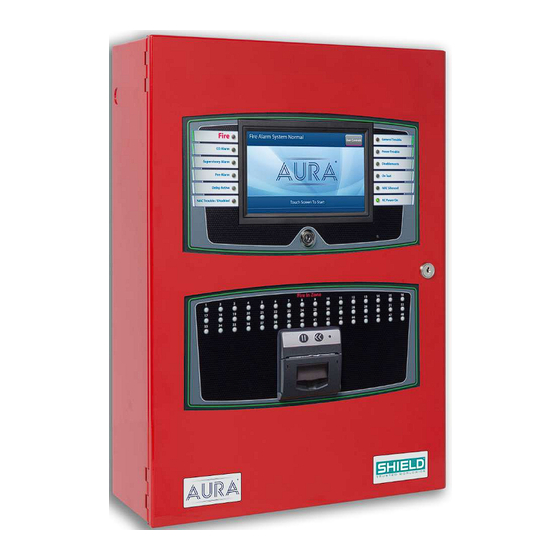
Shield Aura Installation Manual (150 pages)
Fire Alarm Control Panel
Brand:
Shield
| Category:
Control Panel
| Size: 3 MB
Table of Contents
Table of Contents
3
Contents
3
Compliance Information
12
Underwriters Laboratories (UL)
12
Nfpa
12
FM Global Technologies LLC (FM APPROVALS)
12
Introduction
13
Technical Support
13
Limited Returns and Repairs Policy
13
In-Warranty Items
13
Damaged Goods
13
Component Failure
13
Service Replacement Items
13
Out of Warranty Items
14
Customer Repairs
14
Repair Warranties
15
Items Returned for Credit
15
Installation
16
Preparing for Installation
17
Mounting the Aura Fire Alarm Control Panel
19
Removing Cabinet Components
19
Replacing Cabinet Components
22
Connecting and Dressing Cabling
22
Connecting 24V and 14 Conductor Wiring
22
Installing Power Supplies
22
The 5.25 Amp Power Supply
22
The 10.25 Amp Power Supply
23
Connecting Standby Batteries
23
Installing Optional Panel Modules
25
DIP Switch Settings
25
Placement
25
Installing the Network Module
28
Network Connections
28
Fiber Optic Networking
29
Connecting Field Wiring
32
Ferrite Installation
32
Class a SLC Loops
34
Class B SLC Loops
35
Class X SLC Loops
36
Notification Appliances
36
Connecting Notification Appliances
37
Connections for NAC Power Output Modes
38
AUX 24V 1 and aux 24V 2
39
Relay Contacts
40
Network
40
Rs-485 I/O
41
Fire Routing Output 1
41
Prog Input
41
Installing Addressable Devices
43
SLC Detector Spacing
43
SLC Device Detector Sensitivity
43
Detector Calibration / Drift Compensation
43
Addressing an SLC Module
43
Shield Protocol
43
Connecting SLC Devices
44
Shield Protocol
44
Installing Municipal Boxes
45
Testing the Installation
46
Panel Start-Up
46
Loading Configuration
47
Testing the Power Supply
47
Testing the Field Circuits
47
Testing the Panel GUI
48
Panel Tests
48
Lamp & Buzzer Test
49
Display Test
49
System Information
49
Event Log
50
Programming the Panel
51
Loop Explorer 2
51
Overview
52
Required Modules for Minimum Operation and Basic Function
53
System a Panel Module (AUL-9069)
53
System B Panel Module (AUL-9070)
54
Dual Loop Panel Module (AUL-9058)
56
Notification Appliances
57
Synchronization
57
Configuring NAC Outputs
58
Optional Modules and Assemblies
59
Aura Network Module (AUL-9023)
59
Printer (AUL-9068)
60
Zone LED Module (AUL-9071)
60
Channel I/O Interface Card (AUL-9072)
61
Use Case Examples
61
Restrictions
62
Aura Network Vision Annunciator (AUL-9087)
63
Media Gateway™ Panel Module (AUL-9088)
64
Channel Relay Panel Module (AUL-9091)
64
Batteries
65
Standby Battery Type
65
Fascia
66
LED Status Indicators
67
Panel Leds
67
Fire in Zone Indicators
67
Main Back Board (AUL-9022)
69
NAC and aux 24V Terminals
71
Terminals
72
Panel Module Slots
73
Field Terminal Assignments
74
Panel Module Slots
75
Board Slot C
75
Board Slot D
75
Board Slot E
76
Board Slot F
76
Extension Board Power Terminals
77
Network, RS-485 I/O, Fire Routing Output 1, and Prog Input
78
Power Supply Terminals
79
0V Terminals
80
Power Supply Trouble Signaling Connector
80
Supervised Input and Output Terminals
81
Extension Board (AUL-9086)
82
Extension Board Features
84
Panel Module Slots and Terminals
85
LCD Main Processor Board (AUL-9021)
86
Connectors and Ports
87
Switches, LED Indicators, and Internal Buzzer
88
Power Supplies
89
Features
90
DIP Switches
90
5.25 Amp Power Supply
90
10.25 Amp Power Supply
92
Special Application Mode Table
93
Status Indicators
93
Events and Status
94
Fire
94
Trouble
95
Supervisory
96
Disablement
96
Other Events
96
Maintenance and Repair
97
Batteries
98
Replacing Battery Leads
98
Replacing Standby Batteries
98
Removing the Standby Batteries
98
Installing the Standby Batteries
98
Fuses
99
Battery Lead Fuse on 5.25A Power Supply
99
Replacing the Power Supply Fuse
99
Removing the Power Supply Fuse
99
Installing the Replacement Power Supply Fuse
100
Replacing Internal Components
101
Appendix A: Specifications
103
Operating Constraints
104
Electrical
105
AC Input Ratings
105
Power Supply
106
Fuses
106
24 VDC Output Ratings
106
Standby Battery Ratings
106
Ground Trouble Indication
107
System Power
107
Standby and Alarm Current
107
5.25 a Power Supply
107
Battery
108
Rechargeable Standby Battery Circuit
108
Standby Battery Loads
108
Cabling
109
Cable Maximum Parameters for Network
109
RS-485 Serial Data and Terminal Capacity
109
SLC Loop Ratings
110
Main Back Board
111
NAC Outputs
111
Regulated NAC Outputs
111
Special Application NAC Outputs
112
Aux 24V
113
Relay Ratings
114
Network (RS-485)
114
Rs-485 I/O
114
Fire Routing Output 1
114
Prog Inputs
115
Fire Routing Input
115
Fire Routing Output 2
115
Prog Routing Input 1
115
Prog Routing Output
116
Prog Routing Input 2
116
Trouble Routing Output
116
Trouble Routing Input
116
System Information
117
Mechanical
118
Fascia Components
118
Operating Environment
118
Cabinet Housing
119
Slot Standard Enclosure
120
Slot Standard Enclosure
121
Slot Deep Enclosure
122
Slot Deep Enclosure
123
Appendix B: Equipment List
124
Panel Model Numbers
125
Replacement Parts
127
Accessories
128
Loop Devices
129
Special Application NAC Outputs
130
Amseco Compatible NAC Devices
130
Gentex Compatible NAC Devices
131
System Sensor Compatible NAC Devices
132
Wheelock Compatible NAC Devices
133
Maximum Line Impedance
141
Compatible Devices for Auxiliary 24V
141
Appendix C: Calculations
142
Determining the Total Load Current
143
Determining the Standby Battery Capacity
144
Battery Rating Equation
144
Amp Hour Rating
145
Supervising Station Requirements for Combination Systems
146
Glossary
147
Index
149
Advertisement
Advertisement
Related Products
Shield AVR-LCD
Shield AUL-NX10AR
Shield AUL-NX10AB
Shield AUL-NX06AR
Shield neo NX-FACP-1L
Shield neo NX-FACP-2L
Shield neo NX-FACP-4L
Shield Shiel A-XT
Shield Categories
Irrigation System
UPS
Water Heater
Control Panel
IP Camera
More Shield Manuals
Login
Sign In
OR
Sign in with Facebook
Sign in with Google
Upload manual
Upload from disk
Upload from URL