Sign In
Upload
Manuals
Brands
SEW-Eurodrive Manuals
Industrial Equipment
ONP1L
User Manuals: SEW-Eurodrive ONP1L Pump Lubrication
Manuals and User Guides for SEW-Eurodrive ONP1L Pump Lubrication. We have
1
SEW-Eurodrive ONP1L Pump Lubrication manual available for free PDF download: Assembly And Operating Instructions Manual
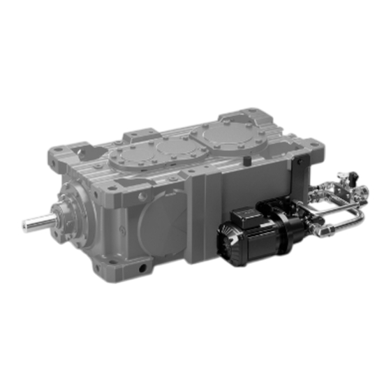
SEW-Eurodrive ONP1L Assembly And Operating Instructions Manual (144 pages)
Industrial Gear Units, Motor Pump with Pressure Lubrication
Brand:
SEW-Eurodrive
| Category:
Industrial Equipment
| Size: 5 MB
Table of Contents
Table of Contents
3
Meaning of Signal Words
5
Structure of Section-Related Safety Notes
5
General Information
5
Structure of the Safety Notes
5
About this Documentation
5
Structure of Embedded Safety Notes
6
Rights to Claim under Limited Warranty
7
Other Applicable Documentation
7
Recycling und Re-Use
7
Product Names and Trademarks
7
Decimal Separator in Numerical Values
7
Copyright Notice
7
Safety Notes
8
Preliminary Information
8
Duties of the User
8
Target Group
9
Designated Use
9
Other Applicable Documentation
10
Safety Symbols
10
Packaging
11
Storage Conditions
11
Exterior Corrosion Protection
11
Internal Conservation
11
Storage and Transport Conditions
11
Motor Pump /ONP1L
13
Functional Description
13
Structure
13
Gear Unit in Mounting Position M1 - Mounting Surface: Oil Supply System on F6
14
Gear Unit in Mounting Position M5 - Mounting Surface: Oil Supply System on F1
14
Scope of Delivery
15
Function
16
Oil Pump
16
Temperature Switch /NTB (Optional)
16
Pressure Switch
16
Nameplate
17
Type Designation
18
Hydraulics Plan
19
Standard
19
Technical Data
20
Dimension Sheets
21
Motor Pump /ONP1L [MM]
21
Interlocking Specifications
24
Gear Unit Enable
24
STOP Gear Unit/Warning
24
Installation/Assembly
25
Mechanical Connection
25
Electrical Connection
25
Control Circuit with Optional Temperature Switch /NTB
26
Wiring Diagram (Schematic Illustration)
26
Main Circuit
27
Pressure Switch
28
Dimensions
28
Electrical Connection
28
Technical Data
28
Limit Temperature for Startup of the Oil Cooling System
29
Notes on Checking the Oil Level
29
Additionally Required Gear Unit Oil
29
Startup
30
Notes
30
Venting the Oil Pump
30
Notes
31
Inspection/Maintenance
31
Inspection and Maintenance Intervals
31
Checking Hose Pipes
32
Permitted Lubricants
33
Structure of the Tables and Abbreviations
33
Explanation of the Various Lubricants
34
Explanation of the Oil Supply Systems and the Oil Viscosity
34
Lubricant Tables
35
Malfunctions/Remedy
38
Notes
38
Possible Failures/Remedy
39
Service
40
Waste Disposal
40
Supplier Documentation
41
Section 1
43
About the Documentation
46
Applicable Documents
46
General
46
Manufacturer Address
46
Symbols
47
Foreseeable Misuse
48
Intended Use
48
Personnel Qualification and Training
48
Safety
48
Basic Safety Instructions
49
Fundamental Hazards
49
Device Description
51
Functional Principle
51
Possible Versions
52
Type Key
55
Rotation and Delivery Direction
56
Type of Seals
57
Special Number
59
Free Shaft End
66
Quench
67
General
68
Technical Data
68
Nominal Sizes
70
Viscosity - Rotation Speed Assignment
71
Operating Pressure of Suction Side and Pressure Side
72
Permissible Pressure Range
72
Compressor Applications
73
Differential Pressure - Viscosity Assignment
73
Max. Suction Side Operating Pressure for Sealing Type 1, 2, 7 and 19
73
Permissible Temperature Range
74
Material Data
75
Compressor Applications
76
Dimensions
77
Weight
77
General
78
Storage
78
Transport
78
Transport and Storage
78
Storage Conditions
79
Installation
80
Safety Instructions for Installation
80
Noise Reduction
81
Gear Pump with Free Shaft End
82
Mechanical Installation
82
Preparation
82
Connection Lines
84
General
84
Suction Line
84
Change of the Direction of Rotation
86
Mounting Connection Lines
86
Pressure Line
86
Tank Line T-Valve
86
Operation Start-Up
87
Preparation
87
Safety Instructions for Start-Up
87
Filling the Quench Chamber
88
Pressure Relief Valve
89
Pressure Relief Valve Adjustment
89
Further Operation Start-Up
90
Removal
91
Safety Instructions for Removal
91
Removal
92
Important Notes about Explosion Protection
93
Maintenance
93
Maintenance Instructions
94
Maintenance Work
94
Maintenance Table
95
Audiometric Monitoring: Unusual Noise
96
Inspection: Add-On Valve Function (if Existing)
96
Inspection: Check the Potential Compensation (if Existing)
96
Inspection: Condition of Operating Fluid
96
Inspection: Device Temperature
96
Inspection: Discharge Flow
96
Inspection: Media Temperature
96
Inspection: Operating Pressure
96
Cleaning
97
Visual Inspection: Condition Gears
97
Visual Inspection: Condition of Housing Parts
97
Visual Inspection: Condition of Plain Bearings
97
Visual Inspection: Filling Level of Liquid Seal (if Existing)
97
Visual Inspection: Leakages
97
Replacing: Other Seals
98
Replacing: Outboard Bearings
98
Replacing: Plain Bearings (Only by Manufacturer)
98
Replacing: Shaft Seal
98
Visual Inspection: Condition of Outboard Bearings
98
Visual Inspection: Condition of Shaft Seal
98
Repairs
99
Safety Instructions for Repair
99
General
100
Detecting and Eliminating Failures
101
Section 2
106
Safety Instructions
107
2�1 Application Area
108
2�2 Operating Principle Flow Monitoring
108
Functions and Features
108
3�1 Installation Location
109
Installation
109
3�2 Sources of Interference in the Pipe System
110
3�3� Mounting Operation
110
Electrical Connection
111
Operating and Display Elements
111
6�1 Change the Switch Point (Optional)
112
Set-Up and Settings for Water
112
6�2 High Flow Adjustment (Optional)
113
7�1 Low Flow Adjustment
113
7�2 Configure the Switching Output
113
Additional Settings (Optional)
113
7�3 Restore the Factory Setting (Reset)
114
7�4 Lock / Unlock the Unit
114
Error During Adjustment
114
Maintenance
115
Operation
115
Scale Drawing
116
Technical Data
116
Operating Instructions Electronic Pressure Sensor for Industrial Applications Uk Pt54Xx/Pu54Xx
124
Safety Instructions
125
Applications
126
Functions and Features
126
Functions
127
Installation
127
Electrical Connection
128
Technical Data
129
Advertisement
Advertisement
Related Products
Sew Eurodrive ORA11B
SEW-Eurodrive OPT11D-150-0
SEW-Eurodrive 3705055
SEW-Eurodrive 3708075IE2
SEW-Eurodrive 3715075IE2
SEW-Eurodrive 3715110IE2
SEW-Eurodrive 3715150IE2
SEW-Eurodrive AR Series
SEW-Eurodrive AT Series
Sew Eurodrive BMG T Series
SEW-Eurodrive Categories
DC Drives
Industrial Equipment
Inverter
Controller
Engine
More SEW-Eurodrive Manuals
Login
Sign In
OR
Sign in with Facebook
Sign in with Google
Upload manual
Upload from disk
Upload from URL