Sign In
Upload
Manuals
Brands
Sero Manuals
Heat Pump
AWA-SS-6
Sero AWA-SS-6 Source Heat Pump Manuals
Manuals and User Guides for Sero AWA-SS-6 Source Heat Pump. We have
1
Sero AWA-SS-6 Source Heat Pump manual available for free PDF download: Installation And Maintenance Instructions Manual
Sero AWA-SS-6 Installation And Maintenance Instructions Manual (54 pages)
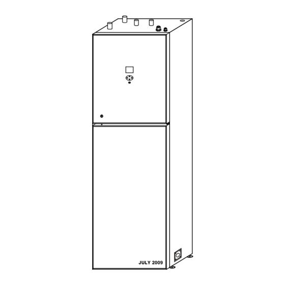
AIR SOURCE HEAT PUMP
Brand:
Sero
| Category:
Heat Pump
| Size: 4 MB
Table of Contents
Table of Contents
3
System Description
4
Principle of Operation
4
Unit Description
5
Principle of Heatpump
6
Control Panel
7
Layout
7
Explanation
7
Functions
8
Symbols
8
General Information for the Installer
9
Transport and Storage
9
Installation
9
Copper Pipe Connecting
9
Inspection of the Installation
9
Pipe Connections
10
General
10
Copper Pipe Connections
10
Pipe Connection (Heating Medium)
11
Pipe Connections (Water Heater)
11
How to Connect the Copper Pipes
12
The Step and Diagram of Collect Refrigerant
13
Pump Capacity Diagrams, Heating Medium Side
14
How to Adjust the Rate of Flow
15
Electrical Connections
16
Connect the Power Cord
16
Wiring of the Terminal (Mode One)
17
Wiring of the Terminal (Mode Two)
17
Connecting the Room Temperature Sensor
18
Connecting the Outside Temperature Sensor
18
Layout of the PCB
19
1.5Mm2 Terminal Connection
19
Part of Wiring Diagram
20
2.5Mm2 Terminal Connection
20
Wiring Diagram( 230V / 50 HZ )
21
Wiring Diagram ( 3X400V / 3 / 50 Hz )
22
Commissioning and Adjusting
23
Preparations
23
Filling and Venting the Heating Medium System
23
Inspection
24
Adjust the Heat Medium Pump
24
Readjusting, Heat Medium Side
24
Emptying the Water Heater
24
Control
25
General Information
25
Menus
26
Main Menu Information
26
Sub-Menu Operation
26
Sub-Menu Heat Curve
27
Sub-Menu Temperature
28
Sub-Menu Integral
28
Degree Minute's(DM) Instruction
29
Sub-Menu Operating Time
31
Sub-Menu Reset
31
Sub-Menuman TEST
31
Sub-Menu DEFROST
32
Adjustments to be Made Regularly
32
Heat Generation-General
32
Adjustment of the CURVE Valve
33
Adjustment of ROOM Valve
35
Adjustment of Part of the Heat Curve
36
Adjustment the MIN and MAX Valve
37
Adjustment of the HEAT STOP Valve
37
Graph of Recent Change in TEMPERATURE
38
Maximum Return Line Temperature
39
Warm Water Production
39
Regular Checks
40
Check of the Operating Mode
40
Checking the Water Level of the Heating System
40
Checking the Safety Valves
41
In the Event of Leakage
41
Alarm Messages
42
Terminology and Abbreviations
43
Description of the Switch Board
44
Dealing with Malfunctions
45
Draining, Heat Medium Side
45
Draining, Water Tank
45
Draining, the Chassis
45
Component Placement
46
Component Positions 1
46
Component Positions 2
47
Component Positions 230 V / 50 HZ
48
Component Positions 3 X 400 V / 3 / 50 HZ
48
List of Components
49
Dimensions
50
Dimensions and Setting-Out Coordinates
50
Dimensions of the AWA-SS-6 Outdoor Unit
51
Dimensions of the AWA-SS-8 Outdoor Unit
51
Dimensions of the AWA-SS-10 Outdoor Unit
51
Dimensions of the AWA-SS-12 Outdoor Unit
52
Dimensions of the AWA-SS-16 Outdoor Unit
52
Accessories
53
Enclosed Kit
53
Technical Specifications
54
Technical Specifications 230 V /3 X 400 V
54
Advertisement
Advertisement
Related Products
SERO DC AWA-SS-15
SERO DC AWA-SS-9
SERO DC AWA-SS-12
SERO DC AWA-SS-7
Sero AWA-SS-8
Sero AWA-SS-10
Sero AWA-SS-16
SERO AWB-SS-9 DC
SERO AWB-SS-12 DC
SERO AWB-SS-15 DC
Sero Categories
Heat Pump
Telephone
More Sero Manuals
Login
Sign In
OR
Sign in with Facebook
Sign in with Google
Upload manual
Upload from disk
Upload from URL