Sign In
Upload
Manuals
Brands
SENTRON Manuals
Measuring Instruments
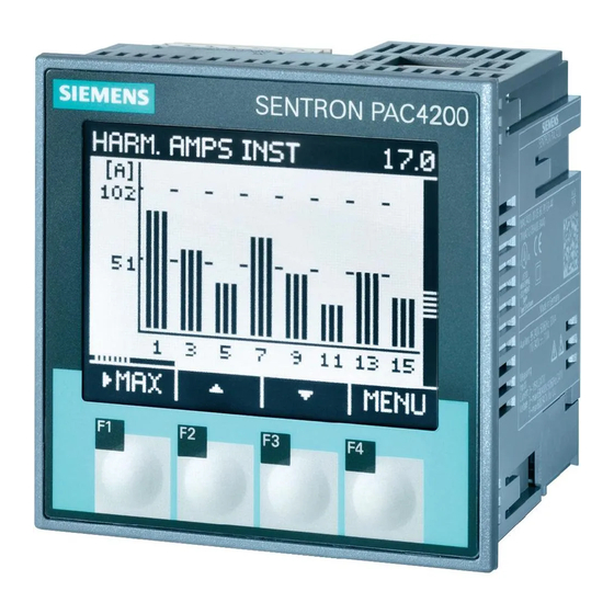
PAC4200
SENTRON PAC4200 Manuals
Manuals and User Guides for SENTRON PAC4200. We have
1
SENTRON PAC4200 manual available for free PDF download: Manual
SENTRON PAC4200 Manual (284 pages)
Power Monitoring Device
Brand:
SENTRON
| Category:
Measuring Instruments
| Size: 9 MB
Table of Contents
Table of Contents
3
SENTRON PAC4200 System Manual, 09/2009, A5E02316180B-02
9
Manual
10
SENTRON PAC4200 System Manual, 09/2009, A5E02316180B-02
11
Manual
12
1 Introduction
13
Purpose of this Document
13
Orientation Aids
13
Components of the Product
14
Contents of the Data Carrier
14
Latest Information and Correction Sheet
14
A5E02316180B
14
Further Documentation
15
2 Safety Instructions
17
Safety Notes
17
3 Description
19
Performance Features of the SENTRON PAC4200
19
Measuring Inputs
24
Measured Variables
25
Table 3- 1 Available Connection Types
25
Table 3- 2 Display of the Measured Variables Depending on the Connection Type
28
Sliding Window Demand Values
31
Other Properties of Measured Variable Representation
32
Load Profile
33
Overview
33
Historical Load Profile
36
Table 3- 3 Historical Load Profile
36
Current Load Profile Data at the Communication Interfaces
37
Synchronization of the Load Profile
37
Additional Information about the Load Profile Data
39
Tariffs
39
Technical Features of the Supply Quality
40
Date and Time
43
Limits
44
Function of the Digital Inputs and Outputs
46
Ethernet Port
48
Slots for Expansion Modules
49
Gateway
50
Slots
52
Password Protection
54
User-Definable Displays
54
Events
55
Table 3- 4 Meaning of the Symbols in the Events List
56
Table 3- 5 the Following Events Are Reported
57
Performance Features of the PAC PROFIBUS DP Expansion Module
60
Performance Features of the PAC RS485 Expansion Module
61
Performance Features of the SENTRON PAC 4DI/2DO Expansion Module
61
4 Operation Planning
63
5 Installation
67
Unpacking
67
Insert Battery
68
Tools
69
Mounting on the Switching Panel
70
Mounting Dimensions
70
Installation Steps
70
Figure 5-3 Installation Step A, Device with Ring Lug Terminals
72
Figure 5-4 Installation Step E, Strain Relief for RJ45 Connector
73
Installing the Expansion Modules
74
Deinstalling
76
Disassembling an Expansion Module
77
6 Connecting
79
Safety Notes
79
Connections
80
Connecting the Cables to the Terminals
86
Connection Examples
87
Grounding of the Ethernet Cable
94
Figure 6-22 Grounding of the Ethernet Cable
95
Connecting the PAC RS485 Expansion Module
96
Connecting the SENTRON PAC 4DI/2DO Expansion Module
98
7 Startup
101
Overview
101
Applying the Supply Voltage
101
Table 7- 1 Connection of Supply Voltage
102
Parameterizing the Device
103
Procedure
103
Language
103
Date and Time
105
Voltage Input
106
Set the Connection Type
106
Table 7- 2 Available Connection Types
106
Measurement Using Voltage Transducers
107
Setting the Conversion Ratio of the Voltage Transducer
108
Setting the Voltage Input
109
Current Input
110
Setting the Conversion Ratio of the Current Transducer
110
Applying the Measuring Voltage
111
Applying the Measuring Current
111
Check the Displayed Measured Values
112
8 Operator Control
113
Device Interface
113
Displays and Operator Controls
113
Figure 8-2 Information Structure and Navigation
116
Display of the Measured Variables
120
Display of the "MAIN MENU
123
Display of the "SETTINGS" Menu
124
Table 8- 1 Assignments of the Function Keys in the "MAIN MENU
124
Table 8- 2 Assignments of the Function Keys in the "SETTINGS" Menu
125
Display of the Device Settings
126
Table 8- 3 Assignments of the Function Keys in the Device Settings Display
126
Edit Mode of the Device Settings
127
Operator Input Steps
128
Operator Input Steps in the Measured Variable Display
128
Table 8- 4 Assignments of the Function Keys in Edit Mode of the Device Settings
128
Operator Input Steps in the "MAIN MENU
130
Operator Input Steps in the "SETTINGS" Menu
131
Operator Input Steps in Device Settings Display
131
Operator Input Steps in Edit Mode of the Device Settings
132
Special Displays
133
Phasor Diagram
133
Table 8- 5 Symbols Used in the Phasor Diagram
133
Table 8- 6 Values in the Phasor Diagram
134
9 Parameterizing
135
Introduction
135
Parameterizing the Operator Interface
135
Groups of Settings
135
Device Information
136
Language and Regional Settings
137
Basic Parameters
137
Power Demand
141
Date / Time
142
Integrated I/Os
144
Communication
149
Table 9- 1 Setting Options in the Field "TARGET" Depending on the Action Selected
149
Display
150
Advanced
151
Password Management
159
Calling Password Management
159
Switch on Password Protection
160
Switch off Password Protection
161
Change Password
161
Password Lost - What to Do
162
Expansion Modules
163
Configuring the PAC RS485 Expansion Module
163
Table 9- 2 Structure of the Setting Versions
164
Configuring the SENTRON PAC 4DI/2DO Expansion Module
165
Table 9- 3 Setting Options
165
Table 9- 4 Performance Calculation
165
Table 9- 5 Status in the "DIAG" Field with Meaning
166
Diagnostics LED of the SENTRON PAC 4DI/2DO Expansion Module
167
Table 9- 6 Status and Fault Indication by the LED
167
10 Service and Maintenance
169
Calibration
169
Cleaning
169
Firmware Updates
169
Replacing the Battery
170
Figure 10-1 "CHANGE BATTERY
171
Figure 10-3 Battery Change
172
Repair
173
Disposal
173
11 Technical Data
175
Digital Outputs
178
Safety Regulations
183
Cable
184
PAC RS485 Expansion Module - Standards
184
Table 11- 1 the Device Meets the Following Standards
184
Table 11- 2 Mechanical Data for the PAC RS485 Expansion Module
185
Table 11- 3 Electrical Data for the PAC RS485 Expansion Module
185
Technical Data for the PAC RS485 Expansion Module
185
Communications Interface of the PAC RS485 Expansion Module
186
Table 11- 4 Ambient and Environmental Conditions
186
Table 11- 5 Technical Data for the Communication Interface
186
Table 11- 6 Connection Types with Associated Conductor Cross-Sections
187
Table 11- 7 Technical Data of the Terminal Block
187
Table 11- 8 Mechanical Data of the SENTRON PAC 4DI/2DO Expansion Module
188
Table 11- 9 Electrical Data of the SENTRON PAC 4DI/2DO Expansion Module
188
Technical Data of the SENTRON PAC 4DI/2DO Expansion Module
188
Table 11- 10 Technical Data of the Digital Inputs
189
Table 11- 11 Technical Data of the Digital Outputs
189
Labeling
190
Labeling on the PAC RS485 Expansion Module
191
Labeling on the SENTRON PAC 4DI/2DO Expansion Module
192
12 Dimension Drawings
193
Dimension Drawings of the PAC RS485 Expansion Module
196
Dimension Drawings of the SENTRON PAC 4DI/2DO Expansion Module
197
Appendix
199
Measured Variables
199
A.1 Measured Variables
199
Load Profile
225
Modbus
225
Measured Variables Without a Time Stamp with the Function Codes 0X03 and 0X04
225
A.2 Load Profile
225
Table A- 1 Measured Variables Available Without a Time Stamp
226
Table A- 2 Meaning of the Abbreviations in the "Access" Column
232
Structure - Digital Inputs Status and Digital Outputs Status with the Function Codes 0X01 and 0X02
233
Table A- 3 Structure - Digital Inputs Status and Digital Outputs Status
233
Table A- 4 Structure - Digital Inputs Status and Digital Outputs Status for an Expansion Module SENTRON PAC 4DI/2DO on Slot 1
233
Structure - Limit Values with the Function Codes 0X01 and 0X02
234
Structure - PMD Diagnostics and Status with the Function Codes 0X03 and 0X04
234
Measured Variables for the Load Profile with the Function Codes 0X03 and 0X04
235
Tariff-Specific Energy Values in Double Format with the Function Codes 0X03, 0X04, and 0X10
237
Tariff-Specific Energy Values in Float Format with the Function Codes 0X03 and 0X04
238
Maximum Values with a Time Stamp and the Function Codes 0X03 and 0X04
239
Minimum Values with a Time Stamp and the Function Codes 0X03 and 0X04
242
Harmonics Without a Time Stamp with the Function Codes 0X03 and 0X04
245
Table A- 18 Harmonics of the Current
247
Table A- 19 Harmonics of the Phase-To-Phase Voltage
248
Harmonics with a Time Stamp and the Function Codes 0X03 and 0X04
249
Table A- 21 Harmonics of the Current
251
Configuration Settings with the Function Codes 0X03, 0X04, and 0X10
254
Value Range for Limit Source
260
Communication Settings with the Function Codes 0X03, 0X04, and 0X10
266
I&M Settings
268
A.3.15 I&M Settings
268
Commands with the Function Code 0X06
269
MODBUS Standard Device Identification with the Function Code 0X2B
270
Correction Sheet
271
A.4 Correction Sheet
271
Table A- 28 Errors, Comments, and Suggestions for Improvements
272
ESD Guidelines
273
Electrostatic Sensitive Devices (ESD)
273
List of Abbreviations
275
Abbreviations
275
C.1 Abbreviations
275
Glossary
277
Index
279
Advertisement
Advertisement
Related Products
SENTRON ConeFET
SENTRON CupFET
SENTRON ISFET
SENTRON LanceFET
SENTRON LanceFET+H
SENTRON MicroFET
SENTRON MiniFET
SENTRON SI400 7400-0
SENTRON SI600 7600-0
SENTRON TITAN
SENTRON Categories
Measuring Instruments
Microcontrollers
More SENTRON Manuals
Login
Sign In
OR
Sign in with Facebook
Sign in with Google
Upload manual
Upload from disk
Upload from URL