Sign In
Upload
Manuals
Brands
Sensor Therm Manuals
Measuring Instruments
METIS H311
Sensor Therm METIS H311 Manuals
Manuals and User Guides for Sensor Therm METIS H311. We have
2
Sensor Therm METIS H311 manuals available for free PDF download: User Manual
Sensor Therm METIS H311 User Manual (64 pages)
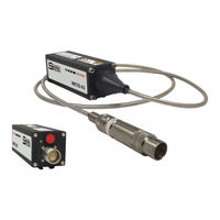
Pyrometers. With 12-pin connector, display and push button device configuration Versions with integrated optics, optical fiber, PID controller, Profibus / Profinet
Brand:
Sensor Therm
| Category:
Measuring Instruments
| Size: 3 MB
Table of Contents
Table of Contents
2
General
4
Information to this Manual
4
CE Conformity and Standards
4
Limitation of Liability
4
Devices with PID Controller
4
Terms of Warranty
4
Copyright
5
Explanation of Symbols
5
Customer Service / Spare Parts
5
Disposal
5
Safety
6
General
6
Electrical Connection
6
Laser Targeting Light
6
Through-Lens Sighting / View Finder
6
Device Labels
6
Responsibility of the Operators
6
Overview
7
Intended Use
7
Scope of Delivery
7
Model Designs
7
Electrical Connection
8
Cable Colors and Pin Assignment (14-Wire Connection Cables)
8
Factory Settings
9
Power Supply
9
Analog Output 1 and 2
10
Configurable Inputs / Outputs
10
Serial Interface RS232 / RS485 (M3: Switchable RS232 / RS485; H3: Only RS485)
11
Interface Converter (Accessory)
12
Shielding
12
Camera Module
12
Devices with Additional Profibus-DP or Profinet Connection
13
Pin Assignment Profibus-DP
13
Pin Assignment Profinet
13
Mechanical Installation
14
Mounting
14
Mounting Optical Fiber / Optics (Only Devices with Optical Fiber)
14
Bending Radius Optical Fiber
14
Winding and Unwinding the Optical Fiber
14
Mounting of Optical Fiber
14
Connect the Optics
15
Ambient Temperature
15
Ratio Technology / Alignment Onto the Measuring Object
16
Alignment with the Laser Targeting Light
17
Alignment with the through Lens Sighting / View Finder
17
Alignment with the Camera Module
18
Setting the Measuring / Focus Distance
18
Manually Focusable Optics
18
Motorized Focus Optics (Only M3)
18
Manually Focusable Fiber Optic Lenses
19
Spot Size Tables
19
Manually Adjusted or Motorized Focus Optics
19
Focusable Fiber-Optic Lenses
20
Calculation of the Spot Size Diameter Outside the Focused Distance
20
Configuring the Pyrometer
21
Displays on the Device
21
Push Button Functions
22
Parameters / Settings
23
Response Time T 90
24
Dynamic Adaptation at Low Signal Levels (Only M3 Devices)
24
Maximum Value Storage (Peak Picker) / Clear Time T
24
Emissivity Slope
24
Switch-Off Level / Signal Strength
25
Switch-Off Verification
25
Dirty Window Alarm
25
Emissivity Ɛ (When Used in Single-Channel Mode)
25
Transmittance
26
Spot Size Fill Factor
26
Temperature Sub Range
26
Temperature Unit
27
Analog Output
27
Test Current
27
Upscale-Burnout (Only Via Software Sensortools)
27
Customize Analog Output (Only Via Software Sensortools)
27
Interface Type (Only M3 Devices)
28
Baud Rate
28
Address
28
Interface Delay / Answer Delay
28
Key Lock
28
Sensortools Software
29
Program Start / Connecting the Pyrometer
29
Software Window
31
Main Window Graphs
31
Control Window
34
Device Settings and Configuration
36
Configurable Inputs / Outputs
37
Service Functions
39
Interface
40
Data Collection (Buffer Mode)
40
Single-Point Adjustment
41
PID Controller Equipment
43
Profibus- / Profinet Equipment
45
Fieldbus Mode Selection for Reading the Pyrometer Data
45
Writing Pyrometer Data
48
Setups
48
Data Playback
49
Communication / Options
50
Spot Size Calculator
50
Sensorflash Software (Update Firmware)
51
Technical Data
52
Storage
53
Dimensions
54
Composition of the Type Number
55
Accessories
56
Maintenance
57
Cleaning
57
Pyrometer Calibration
57
Trouble-Shooting
57
Communication Via Serial Interface / Interface Commands
58
Index
63
Advertisement
Sensor Therm METIS H311 User Manual (56 pages)
Pyrometer
Brand:
Sensor Therm
| Category:
Measuring Instruments
| Size: 3 MB
Table of Contents
Table of Contents
2
1 General
4
Information to this Manual
4
CE Conformity and Standards
4
Limitation of Liability
4
PID Controller
4
Terms of Warranty
4
Copyright
4
Spare Parts
5
Returning Goods
5
Disposal
5
2 Safety
6
Use of the Manual
6
Supplementary Information about the Operation
6
Warning Notes
6
Safety Labels / Symbols
6
Laser Targeting Light
7
Device Labels
7
Electrical Connection
7
Responsibility of the Operators / Process Responsibility
7
3 Overview
8
Intended Use
8
Scope of Delivery
8
Model Design
8
Identification Label
8
4 Electrical Connection
9
Cable Colors and Pin Assignment
9
Factory Settings
9
Power Supply
10
Analog Output 1 and 2
11
Digital Inputs / Outputs and Analog Input
11
Serial Interface RS232 / RS485 (M3: Switchable RS232 / RS485; H3: Only RS485)
12
USB Interface Converter (Accessory)
13
Shielding
14
5 Mechanical Installation
14
Mounting
14
Mounting Optical Fiber / Optics (Optical Fiber Devices)
14
Bending Radius Optical Fiber
14
Winding and Unwinding the Optical Fiber
14
Mounting of Optical Fiber
14
Connect the Optics
15
Ambient Temperature
15
Ratio Technology / Alignment Onto the Measuring Object
16
Alignment with the Laser Targeting Light
16
Setting the Measuring / Focus Distance
17
Focusable Fiber Optics
17
Spot Size Table
18
Focusable Fiber-Optics OQ30-90
18
Coupling and Alignment of Optics in a Processing Optics
19
Adapt the Optics to the Laser Processing Optics
19
Replacement of the Aperture Unit
19
6 Pyrometer Parameters / Settings
20
Emissivity Slope
20
Emissivity Ɛ (When Used in 1-Color Mode)
20
Transmittance
21
Spot Size Fill Factor
21
Switch-Off Level / Signal Strength
22
Switch-Off Verification
22
Dirty Window Alarm
22
Response Time T 90
22
Dynamic Adaptation at Low Signal Levels
22
Storage Mode Maximum Value Storage (Peak Picker) / Clear Time T CL
22
Temperature Sub Range
23
Customize Analog Output
23
Analog Output
23
Test Current
23
Upscale-Burnout
23
Interface Type (Only M3 Devices)
24
Baud Rate
24
Address
24
Temperature Unit
24
Interface Delay / Answer Delay
24
Device Address
24
7 Sensortools Software
25
Program Start / Connecting the Pyrometer
25
Software Window
27
Main Window Graphs
27
Settings for the Fastest Possible Measurement Data Recording
30
Control Window
31
Device Settings and Configuration
32
Digital Input / Output Configuration
33
Service Functions
35
Interface
36
Data Collection (Buffer Mode)
36
Single-Point Adjustment
37
PID Controller
39
Setups
41
Graphical Measurement Data Playback in the Sensortools Viewer
42
Communication / Options
44
Spot Size Calculator
44
8 Sensorflash Software (Update Firmware)
45
9 Technical Data
46
Maximum Value Storage
47
Analog Output 2
47
Digital Input 2
47
Analog Input
47
Dimensions
48
Composition of the Type Number
48
Accessories
49
10 Maintenance
50
Cleaning
50
Pyrometer Calibration
50
Trouble-Shooting
50
11 Communication Via Serial Interface / Interface Commands
51
PID Controller
54
Proportional Band Xp
54
Hold Time
54
Index
55
Advertisement
Related Products
Sensor Therm METIS H322
Sensor Therm METIS M311
Sensor Therm METIS M322
Sensor Therm METIS MF11
Sensor Therm METIS M3F1
Sensor Therm Metis MS 09
Sensor Therm Metis MI 16
Sensor Therm Metis MI 18
Sensor Therm C322
Sensor Therm CAPELLA C3 Series
Sensor Therm Categories
Measuring Instruments
Thermometer
Security Sensors
Controller
More Sensor Therm Manuals
Login
Sign In
OR
Sign in with Facebook
Sign in with Google
Upload manual
Upload from disk
Upload from URL