Sign In
Upload
Manuals
Brands
Seneca Manuals
Media Converter
Z-SG2-L
Seneca Z-SG2-L Manuals
Manuals and User Guides for Seneca Z-SG2-L. We have
2
Seneca Z-SG2-L manuals available for free PDF download: User Manual
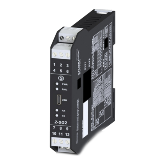
Seneca Z-SG2-L User Manual (56 pages)
DIGITAL LOAD CELL CONVERTER WITH 24 BIT ADC
Brand:
Seneca
| Category:
Media Converter
| Size: 1 MB
Table of Contents
Table of Contents
4
Introduction
7
Description
7
Technical Specifications
8
Led Signals
9
Z-Sg2 / Z-Sg2-L Led
9
Insulation
9
Power Supply
10
Load Cell Connection
11
Or 6-Wire Load Cell Connection
11
Checking the Load Cell Operation
12
Checking Cables with a Digital Multimeter
12
Connection of more Load Cells in Parallel
12
Trimming 4-Wire Load Cells
14
Digital Output / Input Connections
15
Analogue Output Connections (Z-Sg2 Only)
15
Rs485 Port Connections
16
Configuration of the Rs485 Port by Dip Switch
18
Configuration of the Flash Memory Rs485 Port
18
Setting the Baud Rate of the Rs485 Port by Dip Switch
19
Setting the Modbus Station Address of the Rs485 Port by Dip Switch
20
Disconnect the Gnd from the Rs485 by Dip 1 of Sw3
21
Setting the R-C Terminator by Dip 2 of Sw3
21
Complete Configuration with Easy Setup
21
Easy Setup Menu
21
Creating a Project
23
Operating Mode
23
Factory Calibration
23
10.2.1.2. Calibration with Sample Weight
24
Type of Measurement
24
Compression Only (Scales)
24
10.2.2.2. Compression and Traction
24
Unit of Measurement
24
Cell Sensitivity
24
Cell Full Scale
24
Sample Weight
24
Noise Filter
24
Filter Level
25
Advanced Filtering
25
10.2.9.1. Number of Samples of the Moving Average
25
10.2.9.2. Adc Chopping
25
10.2.9.3. Adc Speed
25
10.2.9.4. Noise Variation in Adc Points
26
10.2.9.5. Filter Response Speed
26
Net Weighing Resolution
26
Maximum Resolution
26
Manual
26
Automatic Resolution
26
Digital Input/Output Selection
27
Digital Input Configuration
27
Acquires the Tare
27
External Digital Input
27
Digital Output Operation Mode
27
Cell Full Scale
27
Exceeding the Threshold and Stable Weighing
27
Stable Weighing
28
Modbus Controllable
28
Exceeded Threshold with Hysteresis (Alarm)
28
Stable Weighing Condition
28
Delta Weight
29
Delta Time
29
Net Weighing Alarm
29
Hysteresis
29
Analogue Output Type
29
Voltage
29
Current
29
Analogue Output Configuration
30
Station Address
30
Baud Rate
30
Parity
30
Delay in Replying
30
Sample Weight
30
Automatic Tare Tracker
30
Tare Tracker
30
Adc Value
30
Floating Point Representation of the Measurements
31
First Part H then L
31
FIRST PART L then H
31
Device Test
31
The Data Logger
32
Calibration of the Load Cell with the Easy Setup Software
32
Factory Cell Calibration
32
Factory Calibration with Tare Acquisition from the Field
33
Factory Calibration with Manual Tare Acquisition
33
Cell Calibration with a Sample Weight
34
Usb Port
35
Drivers for Windows Systems
36
Drivers for Linux Systems
36
Firmware Update
36
Load Cell Calibration with Modbus Registers
37
Calibration Procedure with an External Device (Factory Calibration with Tare Acquired from the Field)
37
Calibration Procedure with an External Device
37
Tare)
37
Calibration Procedure with an External Device (Calibration with Sample Weight)
37
Modbus Rtu Slave Communication Protocol
38
Supported Modbus Function Codes
38
Modbus Register Table
40
Numbering of "0-Based" or "1-Based" Modbus Addresses
40
Numbering of Modbus Addresses with "0-Based" Convention
41
Numbering of Modbus Addresses with "1 Based" Convention (Standard)
41
Bit Convention Within a Modbus Holding Register
42
MSB and LSB BYTE CONVENTION WITHIN a MODBUS HOLDING REGISTER
42
Representation of a 32-Bit Value in Two Consecutive Modbus Holding Registers
42
Type of 32-Bit Floating Point Data (Ieee 754)
43
Z-Sg2 / Z-Sg2-L: Modbus 4X Holding Registers Table (Function Code 3)
44
Advertisement
Seneca Z-SG2-L User Manual (54 pages)
DIGITAL LOAD CELL CONVERTER WITH 24 BIT ADC
Brand:
Seneca
| Category:
Media Converter
| Size: 1 MB
Table of Contents
Table of Contents
3
Introduction
6
Description
6
Technical Specifications
7
Led Signals
8
Z-Sg2 / Z-Sg2-L Led
8
Insulation
8
Power Supply
9
Load Cell Connection
10
Or 6-Wire Load Cell Connection
10
Checking the Load Cell Operation
11
Checking Cables with a Digital Multimeter
11
Connection of more Load Cells in Parallel
11
Trimming 4-Wire Load Cells
13
Digital Output / Input Connections
14
Analogue Output Connections (Z-Sg Only)
14
Rs485 Port Connections
15
Configuration of the Rs485 Port by Dip Switch
17
Configuration of the Flash Memory Rs485 Port
17
Setting the Baud Rate of the Rs485 Port by Dip Switch
18
Setting the Modbus Station Address of the Rs485 Port by Dip Switch
19
Setting the R-C Terminator by Sw3 Dip Switch
20
Complete Configuration with Easy Setup
20
Easy Setup Menu
20
Creating a Project
21
Operating Mode
21
Factory Calibration
21
10.2.1.2. Calibration with Sample Weight
22
Type of Measurement
22
10.2.2.2. Compression and Traction
22
Cell Full Scale
22
Cell Sensitivity
22
Noise Filter
22
Sample Weight
22
Unit of Measurement
22
Advanced Filtering
23
Filter Level
23
Compression Only (Scales)
22
10.2.9.1. Number of Samples of the Moving Average
23
10.2.9.2. Adc Chopping
23
10.2.9.3. Adc Speed
23
10.2.9.4. Noise Variation in Adc Points
24
10.2.9.5. Filter Response Speed
24
Net Weighing Resolution
24
Automatic Resolution
24
Digital Input Configuration
25
Digital Input/Output Selection
25
Manual
24
Maximum Resolution
24
Acquires the Tare
25
Cell Full Scale
25
Exceeding the Threshold and Stable Weighing
25
External Digital Input
25
Digital Output Operation Mode
25
Exceeded Threshold with Hysteresis (Alarm)
26
Stable Weighing Condition
26
Modbus Controllable
26
Stable Weighing
26
Current
27
Analogue Output Configuration
28
Automatic Tare Tracker
28
Baud Rate
28
Delay in Replying
28
Parity
28
Sample Weight
28
Station Address
28
Delta Time
27
Analogue Output Type
27
Hysteresis
27
Net Weighing Alarm
27
Delta Weight
27
Voltage
27
Adc Value
28
Floating Point Representation of the Measurements
29
Tare Tracker
28
First Part H then L
29
FIRST PART L then H
29
Device Test
29
Calibration of the Load Cell with the Easy Setup Software
30
Factory Cell Calibration
30
The Data Logger
30
Factory Calibration with Manual Tare Acquisition
31
Factory Calibration with Tare Acquisition from the Field
31
Cell Calibration with a Sample Weight
32
Usb Port
33
Drivers for Linux Systems
34
Drivers for Windows Systems
34
Firmware Update
34
Calibration Procedure with an External Device
35
Load Cell Calibration with Modbus Registers
35
From the Field)
35
Tare)
35
Calibration Procedure with an External Device (Calibration with Sample Weight)
35
Modbus Rtu Slave Communication Protocol
36
Supported Modbus Function Codes
36
Modbus Register Table
38
Numbering of "0-Based" or "1-Based" Modbus Addresses
38
Numbering of Modbus Addresses with "0-Based" Convention
39
Numbering of Modbus Addresses with "1 Based" Convention (Standard)
39
Bit Convention Within a Modbus Holding Register
40
MSB and LSB BYTE CONVENTION WITHIN a MODBUS HOLDING REGISTER
40
Representation of a 32-Bit Value in Two Consecutive Modbus Holding Registers
40
Type of 32-Bit Floating Point Data (Ieee 754)
41
Z-Sg2/Z-Sg2-L: Modbus 4X Holding Registers Table (Function Code 3)
42
Advertisement
Related Products
Seneca ZC-SG
Seneca Z-SG
Seneca Z-SG-L
Seneca Z-SG2
Seneca Z170REG
Seneca Z113-1
Seneca Z-SG3
Seneca ZE-SG3
Seneca Z-8NTC
Seneca Z Series
Seneca Categories
Media Converter
Gateway
I/O Systems
Control Unit
Measuring Instruments
More Seneca Manuals
Login
Sign In
OR
Sign in with Facebook
Sign in with Google
Upload manual
Upload from disk
Upload from URL