Sign In
Upload
Manuals
Brands
Seitron Manuals
Measuring Instruments
CHEMIST 900 RACK
User Manuals: Seitron CHEMIST 900 RACK Analyzer
Manuals and User Guides for Seitron CHEMIST 900 RACK Analyzer. We have
2
Seitron CHEMIST 900 RACK Analyzer manuals available for free PDF download: Use And Maintenance Manual, Use And Maintenance
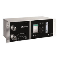
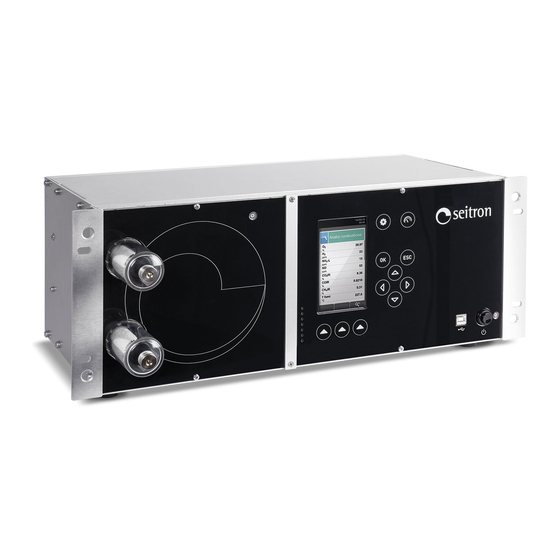
Seitron CHEMIST 900 RACK Use And Maintenance Manual (142 pages)
Gas Analyzer
Brand:
Seitron
| Category:
Measuring Instruments
| Size: 10 MB
Table of Contents
Table of Contents
3
Important Information
7
Information about this Manual
7
Danger Levels and Other Symbols
7
Safety
8
Proper Use of the Product
8
Improper Use of the Product
8
Electrical Connections
9
Electrical Connections
11
Wiring the Signal Lines
12
Connection of the Serial Port RS485 Half Duplex According to MODBUS® RTU
13
Analog Outputs through 37 Poles Connector
14
Connections
17
Connection to PC Via Supplied USB Cable
19
Connection to PC Via Ethernet Cable
20
Wiring Diagram - Back Panel
21
Remote Air Intake Filter Assembly
21
Junctions Assembly - Optional
22
Wiring Diagram
23
Connection to the Nitrogen/Synthetic Air Cylinder
24
Pitot Tube and Flue Gas Sampling Probe Connection
25
Pitot Tube
26
Features of the Smoke Suction Line
27
Features of the Heated Smoke Suction Line (for the Measurement of Nox - Sox)
28
Combustion Air Temperature Probe
29
Draft Measurement
29
Remote Air Suction Spots
29
Product Use
31
Technical Features
33
Product Features
35
General Overview of the Analyzer
35
Working Principle
36
CO Dilution
36
Fuel Types
36
Peltier Module Condensation Assembly (Cooler)
37
Remote Condensate Sink
37
External Dust Filters
37
Dust Filter for the NDIR Bench Protection
37
Remote Air Intake
37
Remote Air Intake Connected in Nitrogen or Synthetic Air
37
Pressure Sensor, Piezoelectric, Temperature Compensated
37
Smoke Suction Pump
38
Condensate Sink Pump
38
Draft Measurement with Sensor Automatic Autozero
38
Temperature Measurements
38
Calculating Total Carbon
38
Autozero Difference in Air, Nitrogen and Synthetic Air
38
Available Software
38
External Size
39
Measurement and Accuracy Ranges
40
Components Description
42
Front Cover
42
Back Panel
44
Startup
46
Preliminary Operations
46
Instrument Power Supply
46
Warning
46
Power on - off
48
Starting the Device
48
Configuration
49
Configuration Menu
49
Configuration=>Analysis
50
Configuration=>Analysis=>Fuel
52
Configuration=>Analysis=>Condensation
53
Configuration=>Analysis=>O Reference
54
Configuration=>Analysis=>No
55
Configuration=>Analysis=>Measure List
57
Configuration=>Analysis=>Autozero
59
Configuration=>Analysis=>Other Configs
60
Configuration=>Analysis=>Other Configs.=>Sample Processing
61
Configuration=>Analysis=>Motor Eff
62
Configuration=>Instrument
63
Configuration=>Instrument=>Time/Date
64
Configuration=>Instrument=>Brightness
65
Configuration=>Instrument=>Buzzer
66
Configuration=>Instrument=>Pump
67
Configuration=>Instrument=>4
68
Configuration=>Instrument=>Co Protection
69
Configuration=>Instrument=>Ndir Bench
70
Configuration=>Instrument
71
Configuration=>Instrument=>Modbus
72
Configuration=>Operator
73
Configuration=>Alarms
75
Configuration=>Information
77
Configuration=>Information=>Sensors
78
Configuration=>Information=>Infoservice
79
Configuration=>Information=>Reminder
80
Configuration=>Diagnostic
81
Configuration=>Diagnostic=>Sensors
82
Configuration=>Diagnostic=>Pump
83
Electrochemical Sensors and IR Bench
84
On-Site Calibration Procedure
85
Configuration=>Diagnostic=>Hardware
94
Configuration=>Diagnostic=>Ndir Bench
95
Configuration=>Diagnostic=>Sample Processing
96
Configuration=>Language
97
Configuration=>Restore
98
Measurements
99
Measurements Menu
99
Measurements=>Velocity
100
Flue Gas Analysis
101
Preliminary Operations
101
Emission Analysis Configuration Mode
101
Performing the Emission Analysis
107
Electrochemical Sensors
108
Cxhy Sensor for the Measure of Unburnt Hydrocarbons (Pellistor)
108
(Single NDIR Sensor)
108
NH 3 Sensor for Measuring Ammonia in Combustion Processes
109
Life of Gas Sensors
111
Gas Sensor Life Table
111
Infrared Bench
112
Infrared Bench for Heat Treatment
112
Troubleshooting
113
Troubleshooting Guide
113
Spare Parts and Servicing
115
Spare Parts
115
Accessories
115
Service Centers
116
Maintenance
117
Routine Maintenance
119
Scheduled Maintenance
119
Cleaning External Dust Filters
120
Replacement of External Anti-Pollution Filter on IR Line
121
Replacement of External Anti-Cleaning Filter on Remote Air Intake
121
Fuse Replacement
122
On-Site Calibration
123
AACSE79 Sensor Factory Calibration
123
Firmware Update
129
Annex
131
Annex a - Fuel Coefficients and Formulas
133
Annex B - Law Directions
134
Annex C - Optional Measures List
135
Warranty Certificate
137
Advertisement
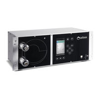
Seitron CHEMIST 900 RACK Use And Maintenance (132 pages)
Gas Analyzer
Brand:
Seitron
| Category:
Measuring Instruments
| Size: 10 MB
Table of Contents
Table of Contents
3
Important Information
7
Information about this Manual
7
Safety Warnings
7
Safety
8
Intended Use of the Product
8
Improper Use of the Product
8
General Features
9
Overview of the Flue Gas Analyzer
9
Description of the Product
11
Operating Principle
11
CO Dilution
11
Types of Fuels
11
Peltier Module Condensation Assembly (Cooler)
11
Remote Condensate Sink
11
External Dust Filters
11
Infrared Bench Protection Dust Filters
12
Remote Air Inlet
12
Pressure Sensor
12
Gas Suction Pump
12
Condensate Drain Pump
12
Draft Measurement with Automatic Sensor Zeroing
12
Temperature Measurements
12
Bluetooth ® Data Link
12
Available Software
13
Electrical Wirings
14
Warnings
14
Wiring the Signal Lines
15
Rtu
16
Analog Outputs through 37 Poles Connector
17
Components Description
18
Front Cover
18
Back Cover
20
Technical Features
22
External Size
24
Measurement and Accuracy Ranges
25
Startup
27
Preliminary Operations
27
Analyzer Power Supply
27
Warnings
27
Connections
29
PC Connection with the Provided USB Cable
29
Wiring Diagram
29
PC Connection with Ethernet Cable
30
Wiring Diagram - Back Panel
31
Remote Air Intake Filter Assembly
31
Optional Junctions Assembly
32
Wiring Diagram
33
Pitot Tube
34
Features of the Smoke Suction Line
35
Features of the Heated Smoke Suction Line (for the Meas. of Nox - Sox)
36
Combustion Air Temperature Probe
37
Draft Measurement
37
Remote Air Suction Spots
37
Power on - off
38
Starting the Device
38
Configuration
39
Configuration Menu
39
Configuration=>Analysis
40
Configuration=>Analysis=>Fuel
42
Configuration=>Analysis=>Condensation
43
Reference
44
Configuration=>Analysis=>No
45
Ratio
45
Configuration=>Analysis=>Measurement Units
46
Configuration=>Analysis=>Measures List
47
Configuration=>Analysis=>Autozero
49
Configuration=>Analysis=>Other Configurations
50
Configuration=>Analysis=>Other Conf.=>Sample Processing
51
Configuration=>Analysis=>Other Conf.=>Sample Selection
52
Configuration=>Instrument
53
Configuration=>Instrument=>Bluetooth
54
Configuration=>Instrument=>Time/Date
55
Configuration=>Instrument=>Brightness
56
Configuration=>Instrument=>Buzzer
57
Configuration=>Instrument=>Pump
58
Configuration=>Instrument=>4
59
Configuration=>Instrument=>Co Sensor Protection
60
Configuration=>Instrument=>Other Configs
61
Configuration=>Instrument=>Ndir Bench
62
Configuration=>Instrument=>Modbus
63
Configuration=>Operator
64
Configuration=>Alarms
66
Configuration=>Information
68
Configuration=>Information=>Sensors
69
Configuration=>Information=>Info Service
70
Configuration=>Information=>Reminder
71
Configuration=>Diagnostic
72
Configuration=>Diagnostic=>Sensors
73
Configuration=>Diagnostic=>Pump
74
Configuration=>Diagnostic=>On Site Calibration
75
On Site Calibration Procedure
76
Configuration=>Diagnostic=>Hardware
83
Configuration=>Diagnostic=>Ndir Bench
84
Configuration=>Diagnostic=>Sample Processing
85
Configuration=>Language
86
Configuration=>Restore
87
Measurements
88
Measurements Menu
88
Measurements=>Velocity
89
Emission Analysis
90
Preliminary Operations
90
Emission Analysis Mode Configuration
90
Performing the Emissions Analysis
95
Sensors
96
Graphic Display Visualization
96
Sensors Arrangement in the Sensors Compartment
97
Sensor Types and Relevant Positioning
98
Gas Sensors Life
99
Gas Sensors Life Table
99
Expandability to 3 Sensors
100
Cxhy Sensor for Measurement of the Unburnt Hydrocarbons (Pellistor)
101
Installing the Cxhy Sensor
101
CO 2 Sensor for Carbon Dioxide Measurement (NDIR Single Sensor)
102
Installing the CO 2 Sensor
102
NH 3 Sensor for Ammonia Gas Measurement in Combustion Processes
103
NDIR Infrared Bench
104
Maintenance
105
Routine Maintenance
105
Preventive Maintenance
105
Internal Parts Access
106
Cleaning External Dust Filters
107
External Dust Filter Replacement on IR Line
108
Fuse Replacement
109
Gas Sensors Replacement
110
Firmware Update
115
Troubleshooting
116
Troubleshooting Guide
116
Spare Parts and Service
118
Spare Parts
118
Accessories
119
Service Centers
120
Annex a
121
Annex B
122
Annex C
123
Annex D
125
Warranty Certificate
127
Advertisement
Related Products
SEITRON CHEMIST 400
Seitron CHEMIST 500
Seitron CHEMIST 600
Seitron CHEMIST 200
Seitron CHEMIST 200 PLUS
Seitron CHEMIST 300
Seitron CHEMIST 600 BE GREEN
Seitron CHEMIST 604 N BE GREEN
Seitron CHEMIST 604 S BE GREEN
Seitron CHEMIST 605 BE GREEN
Seitron Categories
Thermostat
Measuring Instruments
Gas Detectors
Control Unit
Security Sensors
More Seitron Manuals
Login
Sign In
OR
Sign in with Facebook
Sign in with Google
Upload manual
Upload from disk
Upload from URL