Sign In
Upload
Manuals
Brands
Seg Manuals
Relays
MRI3-C
Seg MRI3-C Manuals
Manuals and User Guides for Seg MRI3-C. We have
1
Seg MRI3-C manual available for free PDF download: Manual
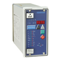
Seg MRI3-C Manual (78 pages)
Digital time overcurrent relay with Control function and auto reclosing
Brand:
Seg
| Category:
Relays
| Size: 3 MB
Table of Contents
Table of Contents
2
Output Relays
3
Digital Inputs
7
Low/High Range of the Digital Inputs
7
Password
8
Code Jumpers
8
Password Programming
8
Function of the Output Relays
8
Front Plates
9
Indicating Leds
9
Adjusting Leds
9
Front Plates (for ER/XR-Relay Types)
10
Indicating Leds
10
Adjusting Leds
10
Working Principle
11
Analog Circuits
11
Digital Circuits
11
Status Descriptions
11
Inactive
11
Reclaim Time" Tr
11
AR-Ready
11
AR-Starting" (Dead Time)
11
AR-Cycle" (Auto Reclosing)
12
AR-Blocked
12
Fast Trip Mode
12
Blocking Mode
12
Activating of AR
12
Description of the Status Transition
12
AR Information Inputs
13
Functional Sequence
13
Switching on MRIK3-C
13
Circuit Breaker Manual Closing
13
Circuit Breaker Manual Open
13
Starting AR
14
Unsuccessful Reclosing
14
Successful Reclosing
14
Repeated Reclosing
14
Supervision of the Circuit Breaker Ready
14
External Blocking
14
Time Sequence Diagrams of MRIK3-C
15
The Unit Is Programmed for Two Shots
15
Manual Closing of the Circuit Breaker to
16
Unsuccessful AR
17
Earth Fault Protection
17
Generator Stator Earth Fault Protection
17
System Earth Fault Protection
17
Earth-Fault Directional Feature
18
(ER/XR-Relay Type)
18
Control Functions
20
Introduction
20
Interlocking / Password for Control Mode
20
Operating Assignment of C.B. Control
20
Changing the Operating Assignment
20
Saving the Operating Assignment
20
Remote Switching on and off of the C.B
20
Switching on or off the C.B. Via the Front
21
Handling of the Control Function
22
Display for the Control Functions
24
LED-Indication Auto Reclosing Conditions
26
Requirement on the Main Current Transformers
27
Operation and Adjustments
28
Displayed Text for Parameter Settings
28
Setting Procedure
30
Parameter Levels
30
System Parameters
30
Presentation of Measuring Values as
30
Primary Quantities on the Display
30
Phase)
30
Display of Residual Voltage U as Primary Quantity
30
Prim Sec
30
Operation Cycle Counter
31
I 2* T Operation Cycle Counter
31
Rated -Frequency
31
Indication of Pickup
31
Parameter Set Changeover Switch (P2)
31
Protection Parameters
32
Pickup Current for Phase Overcurrent
32
Trip Characteristics for the Phase over
32
Tripping Time or Time Factor for the Phase Overcurrent Element
32
Fast/Time Tripping by Switch on of the CB for the Earth Fault Low Set Element
33
Current Setting for High Set Element
33
Trip Delay for High Set Element
33
Pickup Value for Residual Voltage
33
(ER/XR-Relay Types)
33
Pickup Current for Earth Fault Element
33
WARN/TRIP Changeover
33
Time Current Characteristics for Earth Fault
33
Tripping Time or Time Factor for the
33
Earth Fault Element
33
Trip Delay for High Set Element of Earth
34
Fast/Time Tripping by Switch on of the
34
COS/SIN Measurement (ER/XR-Relay Type)
34
AR Parameter
34
Number of AR Shots
34
Fault Time
34
Dead Time
34
Close Impulse Time
34
Reclaim Time (Tr)
34
Fault Time Activation
34
Control Functions
35
Block/Trip-Time
35
Time Delay for Ext. Trip
35
Dead Time for Trip/Restore
35
CB Failure Protection
35
Release of the Pick up Relay for CB
36
Failure Protection
36
Interface Parameters
36
Adjustment of the Slave-Address (RS)
36
Adjustment of the Baud-Rate
36
Adjustment of the Parity
36
Fault Recorder (FR)
37
Fault Recorder
37
Number of Fault Recordings
37
Adjustment of the Trigger Event
38
Pre-Trigger Time
38
Setting of the Clock
38
Additional Functions
39
Blocking the Protection Functions
39
Assignment of the Output Relays
39
Assignment of the AR Functions
42
Function Assignment of the Digital Inputs
44
Description of the Digital Input Function
45
Measuring Value and Fault Indications
46
Measuring Value Indications
46
Units of the Measuring Values Displayed
47
Indication of Fault Data
47
Fault Memory
48
Reset
49
Erasure of the Fault Memory
49
Notes on Relay Tests and Commissioning
50
Connection of the Auxiliary Voltage
50
Testing of Output Relays and Leds
50
Secondary Injection Test
50
Test Equipment
50
Example of Test Circuit for MRI(K)3-C
51
Relays Without Directional Feature
51
Checking the Input Circuits and Measured Values
52
Checking the Operating and Resetting
52
Checking the Relay Operating Time
52
Checking the High Set Element of the
52
(ER/XR Models)
53
Checking the Auto Reclosing Function
54
Checking the Circuit Breaker Position
54
Checking the AR Blocking Function
54
Checking the External Blocking and Reset Functions
54
Testing the External Blocking with
55
Block/Trip Function
55
Test of the CB Failure Protection
55
Primary Test
55
Maintenance
55
Technical Data
56
Measuring Input
56
Common Data
56
Setting Ranges and Steps
57
System Parameter
57
Time Overcurrent Protection (I-Type)
58
Earth Fault Protection (E/X-Type)
58
Earth Fault Protection (ER/XR-Type)
58
AR Parameter
59
Control Function
60
Interface Parameter
60
Parameter for the Fault Recorder
60
Tripping Characteristics
61
Inverse Time Overcurrent Protection Relay
61
Determination of Earth Fault Direction
61
Order Form
64
Advertisement
Advertisement
Related Products
Seg MRIK3
Seg HighTECH Line MRI1IU
Seg MRI1
Seg High Tech MRI3-ITE
Seg High Tech MRI3-ITER
Seg MRIK3-C
Seg HighTECH MRR1
Seg MRP2
Seg MRF3
Seg MRU3-1
Seg Categories
Relays
LED TV
LCD TV
Protection Device
TV
More Seg Manuals
Login
Sign In
OR
Sign in with Facebook
Sign in with Google
Upload manual
Upload from disk
Upload from URL