Sign In
Upload
Manuals
Brands
Securiton Manuals
Smoke Alarm
ASD 531
User Manuals: Securiton ASD 531 Smoke Detector
Manuals and User Guides for Securiton ASD 531 Smoke Detector. We have
1
Securiton ASD 531 Smoke Detector manual available for free PDF download: Technical Description
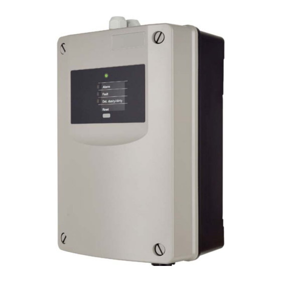
Securiton ASD 531 Technical Description (105 pages)
Aspirating Smoke Detector
Brand:
Securiton
| Category:
Smoke Alarm
| Size: 2 MB
Table of Contents
General
9
Table of Contents
9
1 General
13
Purpose
13
Uses and Applications
14
Abbreviations, Symbols and Terms
14
Product Identification
16
Smoke Sensors Used
17
Hardware / Firmware
17
2 Function
18
General Operating Principle
18
Fig. 1 General Operating Principle
18
Electrical Functional Principle
19
Power Supply
19
Fig. 2 Block Diagram
19
Fan Control
20
Microcontroller
20
Programming / Operation
21
Fig. 3 Workflow for Project-Related Programming
21
Displays
22
Relay
22
Outputs
23
Input
23
Interfaces
23
Airflow Monitoring
24
Smoke Sensor Monitoring
24
Alarm Release
24
Isolating the Smoke Sensor
24
Fault Triggering
25
Event Memory
25
Data Logging on the SD Memory Card
25
Reset Types
26
State Reset
26
Hardware Reset
26
Initial Reset
26
Design
27
Mechanical
27
Fig. 4 Mechanical Design
28
Electrical
29
Hardware / Firmware
30
Fig. 5 Electrical Design
30
List of Materials / Components
31
Packaging
31
4 Planning
32
General Aspects of Planning
32
Standards, Regulations, Guidelines, Approvals
32
Area of Application
32
System Limits
33
Planning Aids
33
Planning with "ASD Pipeflow" Calculation
33
Fig. 6 "ASD Pipeflow" Program Interface
33
Values Table for Planning with "ASD Pipeflow
34
Planning Without "ASD Pipeflow" Calculation
35
Space Surveillance
35
Space Surveillance Applications
35
Principles of Space Surveillance
36
Types of Sampling Pipe Layouts for Space Surveillance
37
Fig. 7 Examples of Planning with "ASD Pipeflow" Calculation
37
Fig. 8 Examples of Planning Without "ASD Pipeflow" Calculation
37
System Limits for Space Surveillance Without "ASD Pipeflow" Calculation
38
Detector Sensitivity Setting Without "ASD Pipeflow" Calculation
38
Fig. 9 Sampling Pipe Definitions
38
System Limits for Planing Without "ASD Pipeflow" Calculation
39
Sampling Holes for Planning Without "ASD Pipeflow" Calculation
39
Fig. 10 Size of Sampling Holes
39
Maintenance Sampling Hole
40
Equipment Monitoring
41
Equipment Monitoring Applications
41
Principles of Equipment Monitoring
41
Examples of Sampling Pipe Layouts for Equipment Monitoring
42
Sampling Fixtures and Sampling Holes in Equipment Monitoring
42
Fig. 11 Equipment Monitoring Layout Variants (Examples)
42
Air Recirculation
43
Fig. 12 Air Recirculation for Differing Climate Zones
43
Settings
44
Fig. 13 Workflow for Project-Specific Programming and Adjustment
44
Electrical Installation
45
Installation Cable Requirements
45
Determining the Conductor Cross-Section
46
Restrictions
47
Environmental Influences
48
5 Mounting
49
Mounting Guidelines
49
Dimensioned Drawing / Drilling Plan for the Detector Housing
49
Fig. 14 Detector Housing Dimensioned Drawing and Drilling Plan
49
Material for the Sampling Pipe
50
Mounting the Detector Housing
51
Opening and Closing the Detector Housing
52
Fig. 15 Open, Closing and Securing the Detector Housing
52
Mounting Positions for the Detector Housing
53
Fig. 16 Mounting Position and Pipe Entries on the Detector Housing
53
Removing the Air Outlet Pipe Plug
54
Turning the Labelling Strip
54
Fig. 17 Removing the Air Outlet Pipe Plug
54
Fig. 18 Turning the Labelling Strips
54
Mounting the Sampling Pipe
55
General
55
Mounting with PVC Tubes and Fittings
55
Mounting with ABS Tubes and Fittings
55
Mounting with Metal Pipes and Fittings
56
Linear Expansion
56
Mounting the Sampling Pipe
57
Fig. 19 Cutting the Tubes
57
Fig. 20 Assembling the Tubes
57
Fig. 21 Vertical Sampling Pipe
57
Fig. 22 90° Bend, Branching Point
57
Mounting for Equipment Monitoring
58
Screw-Free Fastening of the Sampling Pipe
58
Fig. 23 Screw-Free Fastening of a Sampling Fixture
58
Transition to a Flexible Tube
59
Fig. 24 Transition from Fittings to Flexible Tube
59
Creating the Sampling Holes
60
Mounting the Sampling Hole Clips and Maintenance Clips
60
Mounting the Sampling Funnel
60
Fig. 25 Creating the Sampling Holes
60
Fig. 26 Mounting Clips
60
Fig. 27 Using Sampling Funnels
60
Mounting Sampling Stubs for a Ceiling Bushing
61
Fig. 28 Mounting the Ceiling Bushing
61
Mounting the Filter-Box, Filter Unit, Dirt Trap Box, Dust Retaining Box, Water Retaining Box
62
Fig. 29 Mounting Accessory Parts
62
6 Installation
63
Regulations
63
Cable Entry
63
Deploying Smoke Sensors
64
Fig. 30 Deploying the Smoke Sensors
64
Installing Additional Modules XLM 35, RIM
65
Electrical Connection
65
Fig. 31 Installing Additional Modules
65
Terminal Assignment Main Board AMB 31
66
Terminal Assignment for Extended Line Module XLM 35
67
Terminal Assignment for RIM 36 Relay Interface Module
67
Connection Variants
68
Power Supply
68
Reset Input
68
Fig. 32 Types of Power Supply
68
Fig. 33 Reset Input
68
Control
69
Control Via Voltage Supply by Means of Auxiliary Relay
69
Fig. 34 Control Via Supply with Relay
69
Control Via "Reset External" Input
70
Fig. 35 Control Via the "Reset External" Input
70
Connection to the FACP Line
71
Connection to Zone Detection Via al / St Relays
71
Connection to Selective Identification or Addressable Loop Via al / St Relays
71
Fig. 36 Connection to Zone Detection
71
Fig. 37 Connection on Selective Identification or Addressable Loop
71
Connection to Securifire / Integral Addressable Loop from XLM 35
72
OC Outputs
72
Fig. 38 Connection from XLM 35
72
Fig. 39 Connecting the OC Outputs
72
7 Commissioning
73
General
73
Fig. 40 Detector Housing Opened for Commissioning
73
Programming
74
Fig. 41 Control and Indicator Elements on the AMB 31
74
Configuration Options
75
Smoke Sensor Alarm Threshold
75
Air Flow Tolerance & Delay Time
75
Self-Holding Relay
75
Starting up
75
Commissioning Procedure
76
Setting the Alarm Threshold Without "ASD Pipeflow" Calculation
76
Fig. 42 Commissioning Workflow
76
Setting the Alarm Threshold with "ASD Pipeflow" Calculation
77
Setting the Air Flow Tolerance and Delay Time
77
Set Date and Time
78
Initial Reset
78
Isolate Device
78
Logging off Additional Modules XLM 35, RIM 36 and the SD Memory Card
79
Switch Device Inactive
79
Re-Programming
80
Re-Programming on the ASD 531
80
Download New Firmware to the ASD
81
Measurements
81
Reading the Airflow
82
Fig. 43 Airflow Tolerance
82
Testing and Checking
83
Checking the Alarm Release
83
Test Triggerings
84
Commissioning Protocol
84
8 Operation
85
Operation and Display Elements
85
Fig. 44 View of the Operation and Display Elements
85
Functional Sequence of Operation
86
Rotary Switch "Mode" Switch Positions
86
Reset
87
Displays
87
Displays on the Control Unit
87
Indicators on the AMB 31 Main Board
88
SD Memory Card Operation
88
Data Logging on the SD Memory Card
88
Reading out the Event Memory
88
Interpretation of the Event Memory
88
Event Groups
89
Event Codes Within Event Groups
89
Operation and Displays on the XLM 35
91
Fig. 45 XLM 35 Operation and Display
91
General
92
9 Maintenance and Service
92
Cleaning
92
Maintenance Checks and Function Checks
93
4 / 105 ASD 531, Technical Description, T 140 416 en
94
Replacing Units
95
Replacing the Smoke Sensor
95
Replacing the Aspirating Fan Unit
95
Fig. 46 Removing the Aspirating Fan Unit
95
Replacing the Air Flow Sensor
96
Replacing the AMB 31 Main Board
96
Fig. 47 Removing the Air Flow Sensors
96
Disposal
97
Materials Used
97
10 Faults
98
General
98
Warranty Claims
98
Finding and Rectifying Faults
99
Fault States
99
Options
102
Sampling Pipe
102
Use under Extreme Conditions
102
Use of Detector Boxes
102
12 Article Numbers and Spare Parts
103
Detector Housings and Accessories
103
Sampling Pipe and Accessories
103
13 Technical Data
104
List of Figures 14 List of Figures
105
14 List of Figures
105
Advertisement
Advertisement
Related Products
Securiton ASD 535
Securiton ASD 532
Securiton ASD 533
Securiton ASD 535-1
Securiton ASD 535-2
Securiton ASD 535-3
Securiton ASD 535-4
Securiton ASD 535-3 HD
Securiton ASD 535-4 HD
Securiton Genius H
Securiton Categories
Smoke Alarm
Control Panel
Power Supply
Remote Control
Water Filtration Systems
More Securiton Manuals
Login
Sign In
OR
Sign in with Facebook
Sign in with Google
Upload manual
Upload from disk
Upload from URL