Sign In
Upload
Manuals
Brands
SEA TEL Manuals
Antenna
ST88-21 C/Ku-Band TVRO
SEA TEL ST88-21 C/Ku-Band TVRO Manuals
Manuals and User Guides for SEA TEL ST88-21 C/Ku-Band TVRO. We have
2
SEA TEL ST88-21 C/Ku-Band TVRO manuals available for free PDF download: Installation And Operation Manual
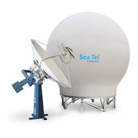
Sea Tel ST88-21 C/Ku-Band TVRO Installation And Operation Manual (145 pages)
DUAL C/QUAD KU-BAND TVRO ANTENNA
Brand:
Sea Tel
| Category:
Antenna
| Size: 7.48 MB
Table of Contents
Table of Contents
5
1 Introduction
11
General Description of System
11
Purpose
11
System Components
11
Dual Antenna Configuration
12
Dual Antenna Arbitrator
13
General Scope of this Manual
13
Quick Overview of Contents
13
2 Site Survey
15
Site Selection Aboard the Ship
15
Antenna Shadowing (Blockage) and RF Interference
15
Mounting Foundation
16
Mounting on Deck or Deckhouse
16
ADE Mounting Considerations
16
Sizing of the Support Pedestal
16
Mounting Height and Fore-Aft Location
17
Mast Configurations
17
Vertical Masts
18
Raked Masts
18
Girder Masts
19
Truss Mast
19
Safe Access to the Ade
19
Below Decks Equipment Location
19
Cables
20
ADE/BDE Coaxial Cables
20
Antenna Power Cable
20
Air Conditioner Power Cable
20
ACU Power Cable/Outlet
21
Gyro Compass Cable
21
Grounding
21
3 Installation
23
General Cautions & Warnings
23
Site Selection Aboard Ship
24
Preparation
24
Opening Your Crates
24
Location of Items Inside the Crates
25
Base Frame and Reflector Crate
25
Pedestal Crate
26
Radome Crate
27
Unpacking the Base Frame and Reflector Crate
27
Unpacking the Pedestal Crate
30
Unpacking the Radome Crate
32
Assembling the Ade
33
Preparing for Assembly of the ADE
33
Sub-Assemble the Base Frame Assembly
33
Sub-Assemble the Bottom Panels of the 126" Radome Assembly
34
Sub-Assemble the Upper Panels of the 126" Radome Assembly
38
Sub-Assemble the Bottom Panels Onto the Base Frame
42
Sub-Assemble the Antenna Pedestal
43
Close the 126" Radome Assembly
45
Hoisting the Ade
47
Prepare the 126" Radome ADE for Lift
47
Installing the Ade
48
Hoist
48
Install Antenna/Radome/Baseframe
49
Installing the below Decks Equipment
49
General Cautions & Warnings
49
Preparing BDE Location
49
Installing the below Deck Equipment
49
Connecting the below Decks Equipment
49
Connecting the ADE AC Power Cable
49
Connecting the BDE AC Power Cables
49
Connecting the ADE if Coaxes
49
Antenna Control Unit Connections
50
13Terminal Mounting Strip (TMS) Connections
50
Other BDE Connections
52
Final Checks
52
Visual/Electrical Inspection
52
Electrical - Double Check Wiring Connections
52
Power-Up
52
Cable Terminations
52
At the Radome
52
Acu & Tms
52
Other BDE Equipment
53
Final Assembly
53
Remove Stow Braces/Restraints
53
Verify All Assembly and Wiring Connections
53
Power-Up the ADE
53
Initialization
53
Home Flag Position
53
Bde
53
Balancing the Antenna
53
Fine Balance and Monitoring Motor Drive Torque
54
Setup
55
4 Basic Setup of the Acu
57
Operator Settings
57
Setup Parameter Display and Entry Menus
57
Track Disp
57
ACU Factory Default Parameter Settings - Stxxx-21 Series Antennas
58
5 Setup - Ships Gyro Compass
59
Gyro Type
59
Updating the Gyro Type
59
Pdating the Gyro Type Parameter
59
If There Is no Ships Gyro Compass
59
6 Determine Internal Tracking Receiver Settings
61
If Tracking Frequency
61
Baud Rate
61
Fec
62
DVB Receiver
62
Tone
62
TVRO Applications
62
Volt
62
TVRO Application
62
Nid
63
7 Setup - Home Flag Offset
65
Electronic Calibration of Relative Antenna Position (Home Flag Offset)
65
You Found a Large AZ TRIM Value
65
You Observe "Home" Pointing Is LEFT of the Bow-Line
66
You Observe "Home" Pointing Is RIGHT of the Bow-Line
66
To Enter the HFO Value in the DAC_2202
67
8 Setup - Targeting
69
Auto Trim
69
Manually Optimizing Targeting
69
El Trim
70
Az Trim
70
Save New Parameters
70
9 Setup - Searching
71
Searching Operation
71
Default Standard (Box) Search Pattern
71
Inclined Orbit Search Pattern
72
No Gyro Search Pattern
73
Changing the Search Parameters
74
Auto Thres
74
El Step Size
74
Az Step Size
74
Step Integral
74
Search Inc
75
Search Limit
75
Search Delay
75
Sweep Inc
75
Save New Parameters
75
10 Setup - Blockage & Rf Radiation Hazard Zones
77
Radiation Hazard and Blockage Mapping (AZ LIMIT Parameters)
77
11 Setup
81
Operator Settings
81
Optimizing Targeting (Auto Trim)
81
Optimizing Targeting (Manually)
81
Radiation Hazard and Blockage Mapping (AZ LIMIT Parameters)
81
Tx Polarity Setup
82
Track Disp
82
12 Functional Testing
83
Acu / Antenna System Check
83
Latitude/Longitude Auto-Update Check
83
Ship Heading - Gyro Compass Following Check
83
Azimuth and Elevation Drive
83
Four Quadrant Tracking Test
83
Blockage Simulation Test
84
13 Maintenance and Troubleshooting
85
Warranty Information
85
Recommended Preventive Maintenance
85
Check ACU Parameters
85
Latitude/Longitude Auto-Update Check
85
Heading Following
85
Azimuth & Elevation Drive
86
Test Tracking
86
Visual Inspection - Radome & Pedestal
86
Mechanical Checks
86
Check Balance
86
Observe Antenna Initialization
86
400Mhz Modem Configuration
87
Mh Zled Indicators
88
Mh Z Modem Signals
88
Pedestal M&C
88
Radio M&C
89
Channel Identification
89
Troubleshooting 400Mhz Modem Communication Faults
90
400Mhz Modem Queries
90
Modem Query Methods
90
Isolating a 400 Mhz Modem Fault Procedure
93
Troubleshooting
95
Theory of Stabilization Operation
95
Series Dual C-Band or Quad Ku-Band TVRO RF Flow
96
Antenna Initialization (ST-21 Series)
96
Antenna Loop Error Monitoring
97
Reference Sensor Testing
98
Reference Sensor Monitoring
99
Open Loop Rate Sensor Monitoring
100
Open Loop Motor Test
101
To Disable/Enable Dishscan
101
Satellite Reference Mode
101
To Read/Decode an ACU Error Code 0008 (Pedestal Function Error)
102
Remote GPS LAT/LON Position
105
Maintenance
106
Balancing the Antenna
106
Remote Tilt
107
To Reset/Reinitialize the Antenna
108
Pedestal Control Unit Configuration - Stxxx-21 Series
109
To Configure the PCU
109
Model Configuration Numbers
109
Antenna Stowing Procedure
110
Antenna Assembly
110
14 St88-21 Technical Specifications
113
8897 Antenna Reflector
113
Feed Assemblies
113
TVRO-21 Dual C-Band / Quad Ku-Band Feed Assembly
113
Stabilized Antenna Pedestal Assembly
114
Mk 2 Pedestal Control Unit (Pcu)
115
Mk 2 Motor Driver Enclosure (Mde)
115
Mh Z Base & Pedestal Unlimited Azimuth Modems (3 Channel )
116
126" Radome Assembly
116
Environmental Conditions (Ade)
117
Cables
117
Antenna Control Cable (Provided from ACU-MUX)
117
Antenna L-Band TVRO if Coax Cables (Customer Furnished)
117
AC Power Cable (Pedestal & Rf Equipment)
117
Gyro Compass Interface Cable (Customer Furnished)
118
Fiber Optic Transmitter (CFE Optional)
118
15 Model St88-21 Drawings
119
Model St88-21 Specific Drawings
119
Advertisement
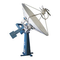
SEA TEL ST88-21 C/Ku-Band TVRO Installation And Operation Manual (127 pages)
DUAL C/QUAD KU-BAND TVRO ANTENNA
Brand:
SEA TEL
| Category:
Antenna
| Size: 12.79 MB
Table of Contents
Table of Contents
7
1 Introduction
13
General Description of System
13
Purpose
13
System Components
13
Dual Antenna Configuration
14
Dual Antenna Arbitrator
15
General Scope of this Manual
15
Quick Overview of Contents
15
2 Site Survey
17
Site Selection Aboard the Ship
17
Antenna Shadowing (Blockage) and RF Interference
17
Mounting Foundation
18
Mounting on Deck or Deckhouse
18
ADE Mounting Considerations
18
Sizing of the Support Pedestal
18
Mounting Height and Fore-Aft Location
19
Mast Configurations
20
Vertical Masts
20
Raked Masts
20
Girder Masts
21
Truss Mast
21
Safe Access to the Ade
21
Below Decks Equipment Location
21
Cables
22
ADE/BDE Coaxial Cables
22
Antenna Power Cable
22
Air Conditioner Power Cable
22
ACU Power Cable/Outlet
23
Gyro Compass Cable
23
Grounding
23
3 Installation
25
General Cautions & Warnings
25
Site Selection Aboard Ship
26
Preparing for the Installation
26
Unpack Shipping Crates
26
Inspect / Inventory
26
Prepare ADE Mounting Location
26
Preparing BDE Location
26
Installing the System Cables
27
126" Radome, Baseframe and Antenna Pedestal System Assembly
27
Preparing the ADE for Lift
30
Installing the Ade
31
Hoist
31
Install Antenna/Radome/Baseframe
31
Installing the below Decks Equipment
31
General Cautions & Warnings
31
Preparing BDE Location
31
Installing the below Deck Equipment
31
Connecting the below Decks Equipment
32
Connecting the ADE AC Power Cable
32
Connecting the BDE AC Power Cables
32
Connecting the ADE if Coaxes
32
Antenna Control Unit Connections
32
13Terminal Mounting Strip (TMS) Connections
32
Other BDE Connections
33
Final Checks
34
Visual/Electrical Inspection
34
Electrical - Double Check Wiring Connections
34
Power-Up
34
Cable Terminations
34
At the Radome
34
Acu & Tms
34
Other BDE Equipment
34
Final Assembly
34
Remove Stow Braces/Restraints
34
Power-Up the ADE
35
Initialization
35
Home Flag Position
35
Bde
35
Balancing the Antenna
35
Fine Balance and Monitoring Motor Drive Torque
36
Setup
37
4 Basic Setup of the Acu
39
Operator Settings
39
Setup Parameter Display and Entry Menus
39
Track Disp
39
ACU Factory Default Parameter Settings - Stxxx-21 Series Antennas
40
5 Setup - Ships Gyro Compass
41
Gyro Type
41
Pdating the Gyro Type Parameter
41
Compass
41
6 Determine Internal Tracking Receiver Settings
43
If Tracking Frequency
43
Baud Rate
43
Fec
44
DVB Receiver
44
Tone
44
TVRO Applications
44
Volt
44
TVRO Application
44
Nid
45
7 Setup - Home Flag Offset
47
Electronic Calibration of Relative Antenna Position (Home Flag Offset)
47
You Found a Large AZ TRIM Value
47
You Observe "Home" Pointing Is LEFT of the Bow-Line
48
You Observe "Home" Pointing Is RIGHT of the Bow-Line
48
To Enter the HFO Value in the DAC_2202
49
8 Setup - Targeting
51
Auto Trim
51
Manually Optimizing Targeting
51
El Trim
52
Az Trim
52
Save New Parameters
52
9 Setup - Searching
53
Searching Operation
53
Default Standard (Box) Search Pattern
53
Inclined Orbit Search Pattern
54
No Gyro Search Pattern
55
Changing the Search Parameters
56
Auto Thres
56
El Step Size
56
Az Step Size
56
Step Integral
56
Search Inc
57
Search Limit
57
Search Delay
57
Sweep Inc
57
Save New Parameters
57
10 Setup - Blockage & Rf Radiation Hazard Zones
59
Radiation Hazard and Blockage Mapping (AZ LIMIT Parameters)
59
11 Setup
63
Operator Settings
63
Optimizing Targeting (Auto Trim)
63
Optimizing Targeting (Manually)
63
Radiation Hazard and Blockage Mapping (AZ LIMIT Parameters)
63
Tx Polarity Setup
64
Track Disp
64
12 Functional Testing
65
Acu / Antenna System Check
65
Latitude/Longitude Auto-Update Check
65
Ship Heading - Gyro Compass Following Check
65
Azimuth & Elevation Drive
65
Four Quadrant Tracking Test
65
Blockage Simulation Test
66
13 Maintenance and Troubleshooting
67
Warranty Information
67
Recommended Preventive Maintenance
67
Check ACU Parameters
67
Latitude/Longitude Auto-Update Check
67
Heading Following
67
Azimuth & Elevation Drive
68
Test Tracking
68
Visual Inspection - Radome & Pedestal
68
Mechanical Checks
68
Check Balance
68
Observe Antenna Initialization
68
400Mhz Modem Configuration
69
Mh Zled Indicators
70
Mh Z Modem Signals
70
Pedestal M&C
70
Radio M&C
71
Channel Identification
71
Troubleshooting 400Mhz Modem Communication Faults
72
400Mhz Modem Queries
72
Modem Query Methods
72
Isolating a 400 Mhz Modem Fault Procedure
74
Troubleshooting
77
Theory of Stabilization Operation
77
Series Dual C-Band or Quad Ku-Band TVRO RF Flow
77
Antenna Initialization (ST-21 Series)
78
Troubleshooting Using Dacremp
79
Antenna Loop Error Monitoring
80
Reference Sensor Monitoring
81
Open Loop Rate Sensor Monitoring
82
Open Loop Motor Test
83
To Disable/Enable Dishscan
84
Satellite Reference Mode
84
To Read/Decode an ACU Error Code 0008 (Pedestal Function Error)
84
Remote GPS LAT/LON Position
87
Maintenance
88
Balancing the Antenna
88
To Adjust Tilt
89
To Reset/Reinitialize the Antenna
90
Pedestal Control Unit Configuration - Stxxx-21 Series
91
To Configure the PCU
91
Model Configuration Numbers
91
Antenna Stowing Procedure
92
14 St88-21 Technical Specifications
95
8897 Antenna Reflector
95
Feed Assemblies
95
TVRO-21 Dual C-Band / Quad Ku-Band Feed Assembly
95
Stabilized Antenna Pedestal Assembly
96
Mk 2 Pedestal Control Unit (Pcu)
97
Mk 2 Motor Driver Enclosure (Mde)
97
126" Radome Assembly
98
Environmental Conditions (Ade)
99
Cables
99
Antenna Control Cable (Provided from ACU-MUX)
99
Antenna L-Band TVRO if Coax Cables (Customer Furnished)
99
AC Power Cable (Pedestal & Rf Equipment)
99
Gyro Compass Interface Cable (Customer Furnished)
100
Fiber Optic Transmitter (CFE Optional)
100
15 Model St88-21 Drawings
101
Model St88-21 Specific Drawings
101
Advertisement
Related Products
Sea Tel ST88
Sea Tel SERIES 10
Sea Tel ST24
Sea Tel ST144-21
Sea Tel SERIES 10 Broadband At Sea
Sea Tel ST94-21
Sea Tel ST94
Sea Tel ST144
Sea Tel ST14
Sea Tel Side Exit
SEA TEL Categories
Antenna
Control Unit
Controller
Industrial Equipment
Marine antenna
More SEA TEL Manuals
Login
Sign In
OR
Sign in with Facebook
Sign in with Google
Upload manual
Upload from disk
Upload from URL