Sign In
Upload
Manuals
Brands
Scout Manuals
Measuring Instruments
MT-700 LiTe
Scout MT-700 LiTe Manuals
Manuals and User Guides for Scout MT-700 LiTe. We have
1
Scout MT-700 LiTe manual available for free PDF download: Operation Manual
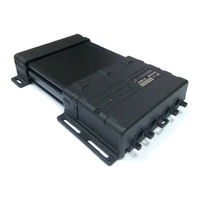
Scout MT-700 LiTe Operation Manual (156 pages)
Fleet monitoring system
Brand:
Scout
| Category:
Measuring Instruments
| Size: 6.01 MB
Table of Contents
Table of Contents
2
List of Abbreviations
3
Introduction
4
Overview
5
Hardware Description
5
МТ-700 Lite Portable
6
Мт-700 Pro 285
6
Package Contents
8
Device Configuration
8
Power Source Recommendations
8
Specification
9
Supply Voltage
9
LED Indication Modes
11
Functional Overview
12
Tracker Modes of Operation
13
Tracker Modes of Operation Scheme
13
I/O and Interfaces
15
Universal Inputs
15
CAN Port
16
RS-485 Port (Scoutnet/J1708/Lls/Rfid/Nmea)
16
Password Protection
18
USB Port (Scoutnet)
18
RS-232 Port (Lls/Can-Log/ VDO/NMEA)
18
Traffic Encryption
19
Using the Voice Call
19
SMS Messages
19
SMS Sending Mode
20
Tracker Mounting Order
21
The Tracker Pre-Installation (SIM Card and Battery Installation)
22
Preliminary Tracker Settings
23
Terminal View from the Connector Jack
23
Tracker Mounting
24
Rubber Burn Mounting
25
Mounting the Burn
25
Cable Sleeves Mounting
26
Recommended Fixing Options
26
Cable Zip Ties
27
Sealing the Tracker
28
Antenna Connection
30
Mounting the GSM Antenna
30
Mounting GPS/GNSS Antenna
30
Mounting Options for GPS/GNSS Antenna
30
Power Connection
31
Interface Jack
32
Auxilary Sensors
33
Sparkproof Parameters
33
Terminal Function Test
34
LED Indication Control
34
Function Test Using a Local “SCOUT Configurator”
35
Remote Control Using “SCOUT Configurator”
35
Terminal Configuration and Control
37
Local Configuration
38
Universal 485 Configurator
39
Configurator
39
Universal Configurator
40
Launch Window of the “SCOUT Configurator”
41
Remote Configuration
42
Configuration through SMS-Commands
43
General Setting Order
43
Ecall Server Settings
48
Voice Call Phone Number
48
SMS Phone Number
49
Terminal Shutdown Threshold
49
Minimal Consumption
50
Power Consumption Modes
50
Event Service Settings
51
GSM Connection Rules
51
Ports and Internal Sensors Configuration
53
Internal Sensors Configuration
54
GPS Receiver Settings («Navigation»)
55
Inertial Navigation
55
Navigation
55
Track Detailing
55
Satellite System Type
56
Modem Parameters
57
Map Source
57
Modem Settrings
57
Millage Based on Navigation
57
Call Control Button
58
Call Indication
58
Accelerometer Settings
60
Moving State
60
Remote Accelerometer Configuration
61
Terminal Response
61
Response from the Terminal
61
Responded SMS
62
Traffic Accident Sensor
63
Ports Configuration
63
Ports
64
Selecting Port Working Mode
65
Digital Inputs P0-P5 Setting
67
Digital Input Parameters
67
Digital Input Settings
68
Battery Disconnect Switch
68
Analogue Inputs Settings on P0-P2
68
«Voltage» Sensor Parameters
69
«Fuel Level» Parameters
69
«Pulse Count» Sensor
70
Counting Sensors on the Р2, Р3 Ports
70
Frequency Counter on the Р2-Р5 Ports
71
«Frequency» Settings
72
«Engine Speed» Parameters
72
PWM Inputs on the Р2-Р5 Ports
73
«PWM Occupation Rate» Sensor Settings
73
«Fuel Sensor» Parameters
73
«Votage» Peak Detector Settings
74
«Fuel Level» Peak Detector
74
Differential Flow Meter
75
Differential Flow Meter on Р2-Р5 Ports
75
1-Wire Sensor Setting on the Р3 Port
75
1-Wire on the P3
76
White List Set up
77
Digital Outputs Р6-Р7 Settings
77
Digital Output Parameters
78
Indication on Р6-Р7 Ports
78
State Indication
78
Drive Style Port
79
Lateral Acceleration Sensor
80
Acceleration/Deceleration Sensor
80
Suspension Bump
81
Body Bump
81
“Engine Block” Sensor
82
Port Status Request for the Р0-Р7 Ports
83
RS-485 Port Settings
83
Data Retransmission
84
Fuel Level Sensor
84
Temperature Sensor
85
Refueller Identification Sensor
86
Driver Identification Sensor
87
«White List» Window
87
Fuel Level
88
Engine Speed
89
NMEA Input Has the Following Parameters
90
CAN Interface Settings
92
Machine Hours (Overall)
93
Axle Load
93
Mobileye Protocol Settings
94
Mobileye Protocol Parameters
94
Vehicle Speed Sensor
95
OBD Protocol Settings
96
Temperature
99
Total Distance
99
Pasing Beam
100
High Beam
100
Seat Belt
100
RS-232 Settings
102
Check Engine
102
VDO Tachograph Settings
103
CAN-LOG Port Parameters
103
«Fuel Level» LLS Sensor
104
LLS Fuel Level Sensor
104
«Temperature» LLS Sensor
105
«Span» Button
105
Span Window
106
Span Procedure
106
Uploading the Span Table to the SCOUT-Explorer
107
Appendix A. MT-700 Pro/ Pro 285 Plug and the Configuration Cable Accordance
108
Appendix B: MT-700 STD/ ENT Plug and the Configuration Cable Accordance
110
Typical Connection Schematics
112
Appendix C: Typical Wiring Schematics
112
Basic Schematic Connection
113
– Basic Scheme
113
Disconnectable Battery Schematic
114
Analogue Fuel Level Sensor
115
Frequency Fuel Level Sensor
116
Digital LLS Fuel Level Sensor
117
Buzzer Connection
118
J1708 and CANJ1939 Connection
119
Engine Speed Sensor Connection
120
Ibutton
121
Appendix D: SMS-Commands
122
Advertisement
Advertisement
Related Products
Scout MT-700 Series
Scout MT-700 STD
Scout MT-700 ENT
Scout MT-700 PRO
Scout Categories
Antenna
Wheelchair
Scales
GPS
Security System
More Scout Manuals
Login
Sign In
OR
Sign in with Facebook
Sign in with Google
Upload manual
Upload from disk
Upload from URL