Sign In
Upload
Manuals
Brands
Savch Manuals
Inverter
S2800-4T11G/15P
User Manuals: Savch S2800-4T11G/15P Control Inverter
Manuals and User Guides for Savch S2800-4T11G/15P Control Inverter. We have
1
Savch S2800-4T11G/15P Control Inverter manual available for free PDF download: User Manual
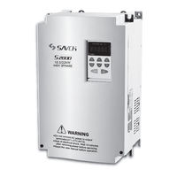
Savch S2800-4T11G/15P User Manual (113 pages)
Vector Control Inverter General Type
Brand:
Savch
| Category:
Inverter
| Size: 21 MB
Table of Contents
Contents
3
Reading Instructions
4
Products Receiving
4
Safety Instructions
5
Notes for Operation
5
Before Wiring
5
During Operation
5
During Check and Maintenance
6
Notes for Operation Environment
7
During Rejection
7
Hardware Descriptions and Installation
8
Operation Environment
8
Correct Configuration
8
Wrong Configuration
8
Model Description
9
Specifications
10
Product Specifications
10
220V Signal / Three Phase Series
10
440V Three Phase Series
10
Standard Specifications
12
Controlling Characteristics
12
Operation Characteristics
12
Environment
12
Applicable Electromagnetic Contactor and Wiring Specifications
13
List of Applicable No-Fuse Breaker for S2800 Series
13
440V Series
14
Application and Description for Ambient Equipments
15
Power Supply
15
No Fuse Breaker
15
Magnetic Contactor
15
Individual Power Supply Bridge
16
Wiring
18
Basic Wiring Diagram
18
AC Motor Drive
18
Main Circuit Terminal Descriptions
19
Terminal Symbol Description
19
External Dimensions
20
Inverter Main Body Figure
21
Keypad Description
25
Description for IP3/IP05 Digital Operation Panel
25
Functions Description of the Keyboard
25
Program Key
25
Indicator Description
26
Description of Function Indicator
26
Description of Unit Indicator
26
Shortcut Multifunction Key
26
Description of Keyboard Operation
27
Parameter Setting
27
Fault Resetting
28
Motor Parameter Self-Learning
28
Password Setting
28
Running State
28
Motor Parameters Self-Learning
29
Running
29
Alarms
29
Quick Debugging
30
Preliminary Operation - Not-Connected with Motor
31
Frequency Command Is Controlled by Keyboard
32
Frequency Command Is Input by Analog Signals
32
List of Descriptions for Functional Parameters
33
Motor Control Parameters
34
Vector Control Parameters
34
V/F Control Parameters
35
Input Terminal Parameters
35
Multi-Velocity Control Parameters
36
Output Terminal Parameters
37
Start-Stop Control Parameters
37
Man-Machine Interface Parameters
38
Enhanced Function Parameters
40
PID Control Parameters
41
Protection Parameters
42
Serial Communication Parameters
42
Description of Functional Parameters
44
User's Parameters
44
Operation Command Channel
44
Keyboard and Terminal UP/DOWN Setting
45
Frequency Command Selection
45
Max. Output Frequency
46
Upper Limitation of Running Frequency
46
Lower Limitation of Running Frequency
46
Keyboard Setting Frequency
46
Deceleration Time 1
47
Schematic Diagram of Time for Deceleration and Acceleration
47
Operation Direction Selection
48
Carrier Frequency Setting
48
Effects Graph of Carrier Frequency on Environment
48
Relation Table of Inverter Type and Carrier Frequencies
48
Function Parameters Restore
49
AVR Function Selection
49
Inverter Type Selection
49
Speed Control Mode
50
V/F Control
50
Torque Control (no PG Vector Control)
50
Motor Control Parameters
50
Motor Rated Power
51
Motor Rated Frequency
51
Motor Rated Rotation Speed
51
Motor Rated Voltage
51
Speed Cycle Proportional Gain 1
52
Speed Cycle Integral Time 1
52
Switch for Lower Point Frequency
52
Speed Cycle Proportional Gain 2
52
Vector Control Parameters
52
VC Slip Compensation Coefficient
53
Torque Upper Limitation Setting
53
V/F Curve Setting
53
Torque Increase
53
V/F Slip Compensation Limitation
54
Reserved
54
Carrier Wave Limitation
54
Schematic Diagram of Manual Torque Increase
54
Function List
55
MI1 Terminal Function Selection
55
MI2 Terminal Function Selection
55
MI3 Terminal Function Selection
55
On-Off Quantity Filtering Times
57
Operation Mode of Terminal Control
57
Three-Wire Control Mode 1
58
Frequency Increase Rate of Terminal UP/DOWN
59
AVI1 Lower Limitation
59
Corresponding Setting of AVI1 Lower Limitation
59
AVI1 Upper Limitation
59
Multi-Steps Speed Control Parameters
60
AVI2/ACI Lower Limitation
60
Corresponding Setting of AVI2/ACI Lower Limitation
60
AVI2/ACI Upper Limitation
60
Logical Diagram of Multi-Steps Speed Operation
61
MO1 Output Selection
61
Relay Output Selection
61
AFM Output Selection
62
AFM Output Limitation
63
Limitation Corresponds to AFM Output
63
Upper Limitation of AFM Output
63
Starting Operating Mode
64
Start Frequency under Direct Starting
64
Duration of Starting Frequency
64
Braking Current before Start
64
Starting Frequency of Stop Braking
65
Waiting Time of Stop Braking
65
DC Braking Current to Stop
65
DC Braking Time on Stop
65
Power-On Terminal Operation Protection Selection
66
User's Password
66
Quick/Jog Key Function Selection
67
STOP/RST Key Stopping Function Selection
67
Running Mode Displaying Parameters Selection
68
Stopping Status Displaying Parameters Selection
68
Rectifier Module Temperature
69
Conversion Module Temperature
69
Software Version
69
Inverter Cumulated Running Time
69
Last Twice Fault Types
70
Last Fault Type
70
Present Fault Type
70
Present Fault Operation Frequency
70
Acceleration Time 2
71
Deceleration Time 2
71
Jog on Operation Frequency
71
Acceleration Time of Jog on Operation
71
Wobble Frequency Width
72
Instant Jump Frequency Width
72
Rise Time of Wobble Frequency
72
Fall Time of Wobble Frequency
72
Times of Fault Auto Reset
73
Interval Period Setting of Fault Auto Reset
73
FDT Level Detection Value
73
FDT Hysteresis Detection Value
73
Frequency Arrival Detection Width
74
Braking Threshold Value Voltage
74
Rotation Speed Displayed Coefficient
74
Low Frequency Threshold Point of Oscillation Suppression
74
Limiting Amplitude Value of Oscillation Suppression
75
Oscillation Suppression
75
PWM Mode Selection
75
Torque Setting Mode
75
Upper Limitation Frequency Setting Selection
76
Torque Setting Channel Selection
76
PID Determined Source Selection
77
Keyboard Presets the PID Set.
77
PID Feedback Source Selection
77
PID Control Parameters
77
PID Output Characteristic Selection
78
Proportion Gain (Kp)
78
Integration Time (Ti)
78
Differential Time (Td)
78
Sampling Period (T)
79
Limitation of PID Control Deviator
79
Proportion Adjustment (P)
79
Integral Time (I)
79
Feedback Broken Line Detection Value
80
Feedback Broken Line Detection Time
80
Dormancy Frequency
80
Dormancy Delay Time
80
Motor Overload Protection Selection
81
Motor Overload Protection Current
81
Coefficient Setting of Motor Overload Protection
81
Frequency Drop Point of Instant Power-Failure
81
Protection Parameters
81
Over Voltage Stall Protection
82
Protection Voltage on over Voltage Stall
82
Over Voltage Stall Function
82
Auto-Current Limitation
83
Frequency Drop Rate of over Current
83
Over Current Stall Function
83
Communication Protocol
84
Protocol Content
84
Application Mode
84
Bus Structure
84
Protocol Specification
84
Communication Frames Structure
85
11-Bit Character Frames
85
10-Bit Character Frames
85
RTU Data Frame Format
86
ASCII Data Frame Format
86
Description of Command Code and Communication Data
87
RTU Assistant Response Information
88
ASCII Host Command Information
88
ASCII Assistant Response Information
89
RTU Host Command Information
89
ASCII Assistant Command Information
93
Communication Frame Error-Checking Method
93
Byte Checking
93
CRC Checking-CRC
94
ASCII Analog Checking
95
Definition of Communication Data Address
95
Response of Wrong Information
98
Meaning of Error Code
98
Modbus Abnormal Code
98
Local Communication Address
99
Communication Baud Rate Setting
99
Data Bit Check Setting
99
Communication Response Delay
100
Time of Communication Overtime Fault
100
Transmission Error Processing
100
Transmission Response Processing
100
Current Auxiliary Level for Brake Valve
101
Output Frequency Multiple Selection
101
Low Voltage Underclocking Level
101
Low Voltage Underclocking Time
101
Troubleshooting
102
Failures & Failure Elimination
102
Troubleshooting for Fault in General
105
Maintenance and Ambient Elements
106
Braking Resistor List
107
Breaker, Cable and Contactor Specifications List
109
Input/Output AC Reactor and DC Reactor Specifications List
109
Input/Output Filter Specifications List
110
Remove the Front Cover
112
Assemble the Front Cover
112
Advertisement
Advertisement
Related Products
Savch S2800-4T1.5G
Savch S2800-4T15G/18.5P
Savch S2800-4T18.5G/22P
Savch S2800-4T110G/132P
Savch S2800-4T132G/160P
Savch S2800-4T160G/185P
Savch S2800-4T185G/200P
Savch S2800-4T400G
Savch S2800-4T560G
Savch S2800-4T280G/315P
Savch Categories
Inverter
Controller
Servo Drives
Computer Hardware
Media Converter
More Savch Manuals
Login
Sign In
OR
Sign in with Facebook
Sign in with Google
Upload manual
Upload from disk
Upload from URL