Sign In
Upload
Manuals
Brands
Santerno Manuals
Inverter
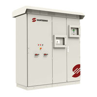
SUNWAY TG1200 1000V TE OD
Santerno SUNWAY TG1200 1000V TE OD Manuals
Manuals and User Guides for Santerno SUNWAY TG1200 1000V TE OD. We have
1
Santerno SUNWAY TG1200 1000V TE OD manual available for free PDF download: Installation Manual
Santerno SUNWAY TG1200 1000V TE OD Installation Manual (139 pages)
MODULAR SUNWAY TG TE OD OUTDOOR THREE-PHASE PHOTOVOLTAIC INVERTER WITH EXTERNAL TRANSFORMER
Brand:
Santerno
| Category:
Inverter
| Size: 7 MB
Table of Contents
Table of Contents
2
Index of Figures
8
Index of Tables
10
1 General Information on the Product
12
Scope of this Manual
12
Figure 1: SUNWAY TG te OUTDOOR Line
12
For Whom this Manual Is Intended
13
Operating Principles
13
Figure 2: Single-Wire Diagram of a Standard SUNWAY TG te Inverter
13
Main Integrated Standard Functions
14
Figure 3: Block Diagram
14
Optional Functions
15
Attached Documentation
15
Preservation of the Documentation
16
Electrical and Mechanical Diagram
16
Table 1: Documentation Supplied with the Product
16
Final Test Certificate
17
Electronic Boards References
17
Symbols Used
18
Definitions
18
2 Caution Statements
19
Precautions for Use and Prohibitions
19
Intended Use
20
Qualified Technical Personnel
20
Specific Dangers Linked to Photovoltaic (Pv) Systems
20
Execution of Work
20
Placing the System in Safety Conditions
21
Personal Protective Equipment
21
Figure 4: System Safety Warning Sign
21
Hearing Protection
22
Electric Connections: Safety Procedure
23
3 Product Identification
24
Checking the Product on Delivery
24
Product ID Code
24
Figure 5: Wooden Crates for the MODULAR SUNWAY TG te Inverter
24
Product Revision Index
25
Serial Number
25
4 Product Configuration
26
Inverter Configuration
26
Earth Bonding of the Pv Field
28
Cabinet Front Controls
28
Ac Section
28
Figure 6: Controls on the Front of the SUNWAY TG te
28
DC Section(S)
29
Control Devices
29
Interface Protection Ip
29
Grid Connection Contactor
30
Figure 7: Interface Protection Diagram
30
DC Input Switch
31
Figure 8: RUN LED on the Display/Keypad
31
Ac Output Circuit Breaker
32
Display/Keypad
32
Figure 9: Display/Keypad
32
Table 2: Function of the Display/Keypad Leds
33
Adjusting the Contrast, Backlight and Buzzer
34
Adjustment of Contrast Only
34
Converter Module
34
Table 3: Display/Keypad Parameter Setup
34
Isolation Control Device
35
Pv Field Not Earthed
35
Figure 10: Single-Line Diagram - Dotted Line Highlighting the Converter Module
35
Figure 11: Isolation Control Board ES942
36
Figure 12: Accessing the ES942 Board
36
Earthed Pv Field
37
Surge Protection
37
DC-Side Protection
37
Table 4: Rotary Switch Position
37
Ac-Side Protection
38
Connectivity
38
Ethernet Connectivity
38
Environmental Measures
38
Table 5: Standard Factory Settings of Environmental Inputs
38
Programmable Digital Outputs
39
Ventilation System
39
Power Supply from Ups
39
DC Input Fuses
39
Table 6: Factory Settings of the Programmable Digital Outputs
39
5 Handling and Assembly
41
Packaging
41
Figure 13: Wooden Crate for Inverter Shipment
41
Figure 14: Wooden Crate for Inverter Rooftop Shipment
41
Handling the Packaged Inverter
42
Handling the Unpackaged Inverter on the Installation Place
42
Figure 15: Inverter Tilting
42
Table 7: Dimensions of the Inverter Complete with Crate and Pallet
42
Figure 16: the Inverter Unpacked
43
Hoisting the Equipment
43
Figure 17: Hoisting the Inverter (TG1200 1000V TE, TG1800 1500V TE)
44
Assembling the Rooftop
45
Figure 18: Hoisting a 3-Door Inverter
45
Settling the Equipment on Its Final Location
45
Figure 19: Rooftop Removed from the Crate
46
Figure 20: Mounting the Eyebolts to Hoist the Inverter Rooftop
46
Figure 21: Removing the Eyebolts and Lifting Brackets from the Rooftop
46
Figure 22: Mounting the Fixing Elements on the Rooftop
47
Figure 23: Placing the Rooftop on the Inverter
47
Environmental Requirements for Storage and Transport
48
Figure 24: Fastening the Rooftop to the Inverter
48
Table 8: Environmental Requirements for Storage and Transport
49
6 Installation and Commissioning
50
Figure 25: Internal View of the SUNWAY TG te Inverter Cabinet
50
Wire Connection Terminal Board
51
General Prescriptions on Connections
51
DC Modules Power Connections
51
Removing the Grilles
51
Table 9: Wire Connection Terminal Board
51
DC Cable Connection
52
Figure 26: DC Power Cable Inlet
52
Ac Modules Power Connections
53
Removing the Grilles
53
Connecting Earth Cables
53
Ac Cables Connection
54
Figure 27: Earth Cables Inlet
54
Figure 28: LV/MV Transformer Connection
55
Table 10: AC Module Output Terminals
55
Connection to the External Transformer
56
Transformer Technical Requirements
56
Figure 29: AC Cable Entry
56
Transformer Application Requirements
57
Application Requirements of the Transformer
57
Table 11: Transformer Technical Requirements
57
Power Supply Connection
58
Figure 30: Location of the Auxiliary Power Supply Terminal Board
58
Auxiliary Power Supply Connection
59
Ups Connection
59
Connection to String Boxes Power Supply (Optional)
60
Signal Connection
60
Accessing the Boards Internal to the Converter
60
Connection of the Digital Inputs and Outputs
60
Figure 31: Removing the Carter to Access the Boards in the Converter
60
Figure 32: Location of the Digital Input Terminal Board
61
Connection to the Environmental Inputs
63
Connecting Custom Environmental Sensors
64
Table 12: Environmental Inputs Connection
64
Figure 33: Environmental Sensors and Field I/Os Expansion Board
65
Table 13: List of Analogue Inputs in ES847 Board
65
Table 14: Function of the 2 DIP-Switches on the Environmental Sensors and I/Os Expansion Board
66
Table 15: Environmental Analogue Channel 1 DIP-Switch Configuration
66
Table 16: Environmental Analogue Channel 2 DIP-Switch Configuration
66
Table 17: Environmental Analogue Channel 3 DIP-Switch Configuration
66
Analogue Inputs to Sensors with Voltage Output
67
Figure 34: Connection to 0 - 10 V Analogue Input
67
Table 18: Environmental Analogue Channel 4 DIP-Switch Configuration
67
Analogue Inputs to Sensors with Current Output
68
Analogue Inputs to PT100 Thermistor
68
Figure 35: Connection to 0 - 100 MV Analogue Input
68
Figure 36: Connection of 0 - 20 Ma (4 - 20 Ma) Sensors to Current Inputs
68
Datalogger
69
Figure 37: Connection of the PT100 Thermistor to the Analogue Channel
69
Figure 38: Data Logger Option Board
69
Connection to the Communications Ports
70
Ethernet Port
70
Figure 39: Location of the Data Logger Option Board
70
Figure 40: Ethernet Cable Path Inside the Converter
71
Figure 41: Ethernet Cable Path Inside the DC Section
71
Serial Link
71
Installation of Voltage Transducers (Vts)
72
Figure 42: Serial Link Terminal Board
72
Reassembling the Protective Grilles
73
Commissioning
73
Figure 43: Protective Grilles Reassembled
73
7 Communications and Remote Monitoring
75
Communication Ports and Protocol
75
Connection Topologies
75
Basic Version
75
Table 19: Communication Ports
75
Optional String Monitoring System
76
Figure 44: Communication Port of the SUNWAY TG te - Basic Version
76
Figure 45: Configuration Diagram of the SUNWAY TG te with Optional Data Logger Board
76
Connection
77
Bus - Main Principles
77
Table 20: Connection Cable
77
Bus - Multidrop Connection
78
Com1 Port
78
Figure 46: Multidrop Connection Diagram
78
Table 21: COM1 Serial Port Connection
78
Figure 47: Location of the SW1 Termination DIP-Switches
79
Table 22: SW1 and SW2 Termination DIP-Switches on RS-485 Galvanic Isolation Board
79
Figure 48: SW1 Termination DIP-Switch
80
Table 23: Voltage Indicator Leds
80
Table 24: FAULT Indicator Leds
80
Ethernet Port
81
Table 25: Ethernet Port Connection
81
Table 26: RJ45 Connector on the Data Logger Board
81
Figure 49: Layout of Pairs in Cat. 5 UTP Cable
82
Figure 50: EIA/TIA 568 Standard Patch Cable, UTP/STP Cat.5
82
Figure 51: EIA/TIA 568 Cross-Over Cable, UTP/STP Cat.5
82
8 Optionals
83
Hard Grounding
83
Figure 52: Hard Grounding Option - Connection of the Positive Pole to Earth
83
Hard Grounding - Additional Safety Warnings
84
Figure 53: Hard Grounding Option - Connection of the Negative Pole to Earth
84
Hard Grounding - Earth Ground Fault Detection
85
Figure 54: Direct Contact with Live Pole (Even under No-Fault Conditions)
85
Figure 55: Direct Contact on a Non-Earthed Pole Due to Earth Fault on the Other Pole
85
Soft Grounding
86
Figure 56: Fault Current Loop in Case of Double Fault to Earth
86
Soft Grounding - Additional Safety Warnings
87
Figure 57: Soft Grounding Option Connection Schematic
87
Zone Monitoring
88
Figure 58: Direct Contact with Live Pole (Even under No-Fault Conditions)
88
Figure 59: Direct Contact on a Soft Grounded Pole
88
DC Emi Filter
89
Ac-Side Spds
89
Figure 60: Zone Monitoring
89
Figure 61: DC EMI Filter
89
Ac Insulation Check
90
Compatibility with Single Secondary for Multi-Mppt Products
90
Self-Power Supply
90
String Monitoring
90
Independent Output Power Measurement (Wattmeter)
90
Sunway Bridge
91
Ac Emi Filter
91
Fuse-Holders
91
External Cooling System Control
91
600 DC Input Components Dimensioning
92
DC Input Fuses Dimensioning
92
Figure 62: Fuse Configuration Example as in the Final Test Certificate
92
DC Input Cable Dimensioning
93
Table 27: Trip Time of NH1-XL Fuses
93
Figure 63: Short-Circuit Occurring Upstream from the Inverter
94
10 Maintenance
95
Maintenance Sheet
95
Reading the Fault List Archives
96
Checking the External and Internal Conditions
96
Table 28: Maintenance Sheet
96
Table 29: Integrated DC- Parallel Maintenance Sheet
96
Air Filter Maintenance
97
Figure 64: Replacing the Filter Felts
98
Figure 65: Removing the Carter Protecting the Air Outtake Grilles
99
Checking the Emergency Stop Button
100
Checking the Door Microswitches
100
Figure 66: Filter Replacement
100
Checking the Seals, Locks and Hinges
101
Checking the Fans
101
Converter Fans
101
Cabinet Fans
102
Checking Control and Auxiliary Voltages
102
Checking 24Vdc
102
Checking 48Vdc
102
230Vac Auxiliary Power Supply
102
Checking the Relays, Fuses and Disconnect Switches
103
Checking the Spds
103
Figure 67: Checking the 110 Vac Control Power Supply
103
Calibration of Environmental Sensors
104
Checking the Tightening Torque
104
Checking the Status Switches for DC Inputs Fuses
104
Figure 68: Surge Protective Device
104
Figure 69: Testing of DC-Parallel Fuse Status Switch
105
11 Troubleshooting
106
Self-Diagnostics
106
Malfunctioning at Start-Up
106
The Inverter Has Stopped by Itself
106
The Inverter Does Not Start When the Start Button Is Pressed
106
The Pv Ok Led Is off
106
The Grid Ok Led Is off
107
Isolation Loss Detected
107
Malfunctioning During Operation
107
The Inverter Does Not Produce the Power Expected
107
The Inverter Trips
107
Malfunction of Communication Ports
108
Serial Communication Problems
108
Table 30: RS485 Galvanic Isolation Board Self-Diagnosis Leds
108
Ethernet Communication Problems
109
Safety Devices Tripped
109
Ac Circuit Breaker Tripped
109
Figure 70: ES914 Isolation Board
109
DC Disconnection Switch Tripped
110
Spds Tripped or Fuses Blown
110
Blown Earth Fuses for Negative or Positive Earthed Options
110
Replacing a Fuse in the DC Sections
110
Figure 71: Extracting the Fuse: Disconnection of a Microswitch and Handle for Removing the Fuse
111
General Principles in the Event of Failure
112
Figure 72: Extracting the Fuse: Using the Isolated Handle for Removing the Fuse
112
Figure 73: Extracting the Fuse: Using the Isolated Handle for Removing the Fuse
112
Fault Analysis
113
Fault Containment
113
DC Section Parallel Fault Analysis
114
How to Contact the Customer Service
114
12 Technical Data
115
Nameplate
115
Installation Specifications
115
Figure 74: Example of a Nameplate of a SUNWAY TG te Inverter
115
Clearance
116
Table 31: Installation Specifications for MODULAR SUNWAY TG te OD
116
Table 32: SUNWAY TG te Noise (1M; Tamb=25°C)
116
Electrical Specifications
117
Figure 75 : Minimum Clearance
117
Table 33: SUNWAY TG te OUTDOOR Electrical Specifications
117
Sunway Tg 1000V te Od
118
Table 34: Technical Data for SUNWAY TG 1000V te by Model
118
Sunway Tg 1500V te Od
119
Table 35: Technical Data of SUNWAY TG 1500V te for TG 900, TG 1800 Models
119
Figure 76: Temperature Derating (at Sea Level)
120
Maximum Voltage Derating
120
Rated Current Derating and Uprating
120
Table 36: Maximum DC Voltage Based on Altitude
120
Figure 77: Coefficient Kt for Temperature Derating (at Sea Level)
121
Figure 78: Short Circuit Localization in the SUNWAY TG te Inverters
121
Short-Circuit Current Contribution
121
Inverter Views
122
Installed Converter Module
122
Figure 79: Maximum Short-Circuit Time-Current Mask
122
Table 37: Inverter Views
122
Inverter Ventilation System
123
Dimensions and Weights
123
Packaged Inverter
123
Table 38: Converter Module
123
Table 39: SUNWAY TG te Ventilation Technical Data
123
Table 40: Classification of the Felt Filter Installed in the Air Intake Grilles
123
Inverter Without Packaging
124
Table 41: SUNWAY TG te Dimensions and Weights
124
Table 42: Handling Methods of the Packaged Inverter
124
Table 43: Dimensions and Weights of the SUNWAY TG te Inverters
124
Connection of Power and Signal Cables
125
DC Connection - Input Cables
125
Table 44: Handling Modes
125
Table 45: Input DC Cable Connection Data
125
Ac Connection - Output Cables
126
Connection of Earth Cables
126
Table 46: Technical Data for AC Output Cables
126
Connection of Auxiliary Power Supply Cables
127
Connecting the Ups
127
Table 47: Technical Data for Earth Cables
127
Table 48: Technical Data for Auxiliary Power Supply Cables
127
String Box Power Supply
128
Input/Output Signals Connection
128
Environmental Inputs Connection
128
Pv-Side Spd Specifications
128
Table 49: Technical Data for Power Supply from UPS
128
Table 50: Technical Data for Power Supply from UPS
128
Table 51: Signal Cable Technical Data
128
Table 52: Environmental Inputs Technical Data
128
Grid-Side Spd Configuration
129
Control Board
129
Table 53: SPD Technical Specifications
129
Table 54: Terminals 1 - 13 Available on the Control Board
131
Environmental Sensors and Field I/Os Expansion Board
132
List of Signals to Terminal Board
132
Table 55: Terminals 14 - 34 Available on the Control Board
132
Electrical Specifications
135
Table 56: Terminals Available on the Environmental Sensors and Field I/O Board
135
Table 57: Analogue Inputs Configured in 0 - 10 V Mode
135
Table 58: Analogue Inputs Configured in 0 - 100 Ma Mode
136
Table 59: Analogue Inputs Configured in 0 - 100 MV Mode
136
Table 60: Analogue Inputs Configured as Temperature Measurement with PT100
137
Table 61: Specifications of the Analogue Power Supply Outputs
137
Table 62: Specifications of the Digital Power Supply Outputs
137
13 Declarations of Conformity
138
14 Annexes
139
Revision Index
139
Advertisement
Advertisement
Related Products
Santerno SUNWAY TG610 1000V TE OD
Santerno SUNWAY TG900 1500V TE OD
Santerno SUNWAY TG1800 1500V TE OD
Santerno 4600TL
Santerno 5000TL
Santerno 6000TL
Santerno 7500TL
Santerno SINUS MINI Series
Santerno SINUS VEGA 2S
Santerno SINUS VEGA 4S
Santerno Categories
Inverter
Controller
DC Drives
Media Converter
Control Unit
More Santerno Manuals
Login
Sign In
OR
Sign in with Facebook
Sign in with Google
Upload manual
Upload from disk
Upload from URL