Sign In
Upload
Manuals
Brands
Sakai Manuals
Construction Equipment
SW880-1
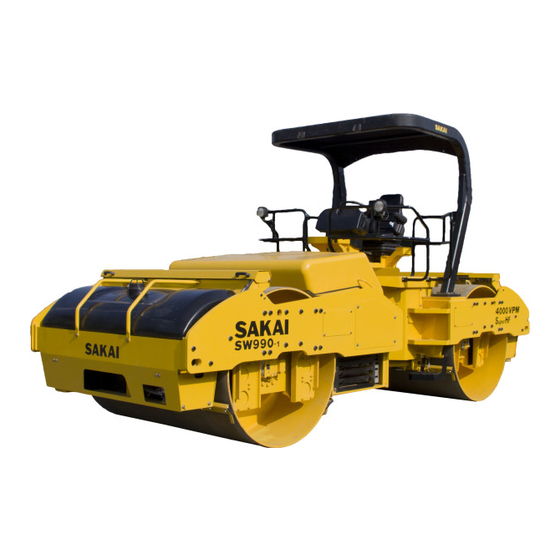
Sakai SW880-1 Smooth Drum Compactor Manuals
Manuals and User Guides for Sakai SW880-1 Smooth Drum Compactor. We have
2
Sakai SW880-1 Smooth Drum Compactor manuals available for free PDF download: Shop Manual, Operator's Manual
Sakai SW880-1 Shop Manual (428 pages)
Brand:
Sakai
| Category:
Construction Equipment
| Size: 55.99 MB
Table of Contents
Table of Contents
5
Safety
15
General Safety
17
Understanding the Safety Symbols and Words
17
General
17
Qualifications of Operators and Maintenance Personnel
18
Safety Practices and Policies
18
Pre Start Inspection
19
Safety Instructions
19
Operating
20
Starting
20
Stopping
20
Maintenance
21
Transporting the Machine
23
Specifications
25
Specification Data
28
Sw880
28
Sw990
32
Table of Standard Values
35
Engine
35
Propulsion
35
Hydraulic System
35
Steering
36
Brakes
36
Capacities
36
Fuel and Lubricants Specification
37
Rating
37
Recommended Lubricants
37
Tightening Torque Chart
38
Engine and Controls
39
Engine
41
Engine Mount
41
Fuel System
42
Control System
43
Forward-Reverse Control
43
Pump Mount
44
Installation of Pump
45
Hydraulic Systems
47
System Circuit Diagram
50
Graphic Symbols for Hydraulic Circuits
50
Hydraulic Circuit Diagram
53
Propulsion Hydraulic System
55
Propulsion Hydraulic Piping
55
Propulsion Hydraulic Piping (1)
55
Propulsion Hydraulic Piping (2)
57
Hydraulic Component Specifications
60
Hydraulic Pump Assembly (Propulsion + Vibrator)
60
Propulsion Hydraulic Motor (Front)
62
Propulsion Hydraulic Motor (Rear)
64
Valve Block
66
Vibrator Hydraulic Piping
67
Vibrator Hydraulic Piping (1)
67
Vibrator Hydraulic System
67
Vibrator Hydraulic Piping (2)
69
Vibrator Hydraulic Piping (3)
71
Hydraulic Component Specifications
73
Vibrator Hydraulic Motor
73
Vibrator Valve Block
74
Steering System
77
Steering Hydraulic Piping
77
Steering Wheel
79
Hydraulic Component Specifications
80
Orbitrol
80
Steering • Charge Pump
81
Electrical System
83
PRECAUTIONS for Work
85
Wire Numbers, Wire Sizes, Wire Colors and Connectors Shown in Electrical Circuit Diagram, Wiring Harness Layout and Wiring Harnesses
85
Electrical Equipment Installation
86
System Circuit Diagram
87
Electrical Circuit Diagram
87
Electrical Components
89
Battery Layout
89
Wiring Harness Layout (1)
91
Wiring Harness Layout (2)
93
Wiring Harness Layout (3)
95
Wiring Harnesses
96
Main Harness (1)
96
Main Harness (2)
98
Fuse • Relay Harness
100
Engine Harness
102
Battery Harness
104
Front Frame Harness
106
F-R Lever Harness
108
Panel Harness (L)
110
Panel Harness (R)
112
Floor Bord Harness
114
Starter Relay Harness
116
Torque Control Box Harness
117
Water Spray Pump (R) Harness
118
Electrical Component Specifications
119
Potentiometer
119
Exact Meter
120
Resistor Unit
121
Lever Switch
122
Fuse Box
123
Combination Meter
124
Vibratory Drum
125
Precautions for Disassembly and Reassembly
127
Removal and Installation of Vibratory Drum
129
Removal of Vibratory Drum
129
Installation of Vibratory Drum
134
Vibratory Drum Assembly
137
Disassembly and Reassembly of Vibratory Drum
137
Disassembly of Vibratory Drum
137
Reassembly of Vibratory Drum
150
Brake
171
Brake Pedal
173
Brake System
174
Operator Station
175
Floorboard
177
Structure of Operator Station
177
Adjustment of Swivel Lock Release Pedal
178
Water Spray System
179
Water SPRAY PIPING
181
Inspection and Adjustment
183
Safety Precautions for Inspection and Adjustment
185
Preparation for Inspection and Adjustment
185
Precautions for Inspection and Adjustment
185
Warm-Up
185
Inspection and Adjustment of Engine Related Items
185
Measurement and Adjustment of Propulsion Circuit Pressure
186
Measurement
186
Adjustment
187
If Pressures on both Forward and Reverse Sides Deviate from
187
If Pressure on Either the Forward or Reverse Side Deviates from
188
Maximum Circuit Pressure Range
188
Measurement
189
Measurement and Adjustment of Propulsion Charge Circuit Pressure
189
Adjustment
190
Measurement of Propulsion Servo Circuit Pressure
191
Measurement
191
Measurement
192
Measurement of Parking Brake Release Pressure
192
Measurement
193
Measurement and Inspection of Vibrator Circuit Pressure
193
Inspection
194
Inspection of High Pressure Relief Valves Installed in Vibrator Pump
194
Measurement
196
Measurement and Inspection of Vibrator Charge Circuit Pressure
196
Inspection
197
Measurement and Inspection of Steering Circuit Pressure
198
Measurement
198
Inspection
199
Measurement of Hydraulic Pump Case Pressure
200
Measurement of Propulsion Pump Case Pressure
200
Measurement of Vibrator Pump Case Pressure
201
Measurement
202
Measurement of Propulsion Motor Case Pressure
202
Measurement
203
Measurement of Vibrator Motor Case Pressure
203
Adjustment of Disc Spring Tension
204
Adjustment of F-R Lever Operating Force
204
Adjustment of F-R Lever Potentiometer
204
Adjustment of Steel Ball Thrust
205
Adjustment of Potentiometer
206
Adjustment of Potentiometer 1 Voltage When F-R Lever Is in "N
206
Adjustment of Potentiometer 1 Voltage When Forward Switch Operates
207
Adjustment of Potentiometer 1 Voltage When Reverse Switch Operates
208
Troubleshooting
209
Safety Precautions for Troubleshooting
211
Important Information for Troubleshooting
211
Before Starting
212
Wire Number and Color Code
212
Electrical System Troubleshooting
213
When Performing Electrical System Fault Diagnosis
213
Precautions to Take During Electrical Circuit Fault Diagnosis
213
Inspection Procedures Using a Tester
214
Inspection of Electrical System
219
Fault Codes
221
Fault Detection
221
Fault Lamps
221
Flash out of Fault Codes
222
Fault Code List
223
Description of Error Codes
232
Error Codes
232
Error Code List
233
Engine
235
Engine will Not Start (Starter Motor Does Not Run) 1/17
235
Engine will Not Start (Starter Motor Does Not Run) 2/17
237
Engine will Not Start (Starter Motor Does Not Run) 3/17
239
Engine will Not Start (Starter Motor Does Not Run) 4/17
241
Engine will Not Start (Starter Motor Does Not Run) 5/17
243
Engine will Not Start (Starter Motor Does Not Run) 6/17
245
Engine will Not Start (Starter Motor Does Not Run) 7/17
247
Engine will Not Start (Starter Motor Does Not Run) 8/17
249
Engine will Not Start (Starter Motor Does Not Run) 9/17
251
Engine will Not Start (Starter Motor Does Not Run) 10/17
253
Engine will Not Start (Starter Motor Does Not Run) 11/17
255
Engine will Not Start (Starter Motor Does Not Run) 12/17
257
Engine will Not Start (Starter Motor Does Not Run) 13/17
259
Engine will Not Start (Starter Motor Does Not Run) 14/17
261
Engine will Not Start (Starter Motor Does Not Run) 15/17
263
Engine will Not Start (Starter Motor Does Not Run) 16/17
265
Engine will Not Start (Starter Motor Does Not Run) 17/17
267
Engine will Not Start (but Starter Motor Runs)
269
No Charging
271
Grid Heater Does Not Work
271
Starter Motor Runs Even When F-R Lever Is Not at "N" and
273
Engine Speed Cannot be Switched
273
Propulsion
275
Machine and Engine Suddenly Stops 1/11
275
Machine and Engine Suddenly Stops 2/11
277
Machine and Engine Suddenly Stops 3/11
279
Machine and Engine Suddenly Stops 4/11
281
Machine and Engine Suddenly Stops 5/11
283
Machine and Engine Suddenly Stops 6/11
285
Machine and Engine Suddenly Stops 7/11
287
Machine and Engine Suddenly Stops 8/11
289
Machine and Engine Suddenly Stops 9/11
291
Machine and Engine Suddenly Stops 10/11
293
Machine and Engine Suddenly Stops 11/11
295
Machine and Engine Suddenly Stops in Automatic Speed Mode 1/2
297
Machine and Engine Suddenly Stops in Automatic Speed Mode 2/2
299
Machine Moves Neither Forward nor Backward 1/6
301
Machine Moves Neither Forward nor Backward 2/6
303
Machine Moves Neither Forward nor Backward 3/6
305
Machine Moves Neither Forward nor Backward 4/6
307
Machine Moves Neither Forward nor Backward 5/6
309
Machine Moves Neither Forward nor Backward 6/6
311
Machine Speed Cannot be Changed
313
Auto Speed Function Does Not Work 1/9
315
Auto Speed Function Does Not Work 2/9
317
Auto Speed Function Does Not Work 3/9
319
Auto Speed Function Does Not Work 4/9
321
Auto Speed Function Does Not Work 5/9
323
Auto Speed Function Does Not Work 6/9
325
Auto Speed Function Does Not Work 7/9
327
Auto Speed Function Does Not Work 8/9
329
Auto Speed Function Does Not Work 9/9
331
Brake Cannot be Released
333
Brake Does Not Work
335
Emergency Exit Propulsion Switch Does Not Work
337
Vibration
339
No Vibration Occurs 1/3
339
No Vibration Occurs 2/3
341
No Vibration Occurs 3/3
343
Vibration Frequency Cannot be Switched 1/3
345
Vibration Frequency Cannot be Switched 2/3
347
Vibration Frequency Cannot be Switched 3/3
349
Continuous/Automatic Vibration Mode Cannot be Switched 1/2
351
Continuous/Automatic Vibration Mode Cannot be Switched 2/2
353
Front and Rear Vibratory Drums Cannot Perform One-Drum Vibration
355
Exact Meter
357
Exact Meter Indicator Lamp Does Not Illuminate While Driving 1/9
357
Exact Meter Indicator Lamp Does Not Illuminate While Driving 2/9
359
Exact Meter Indicator Lamp Does Not Illuminate While Driving 3/9
361
Exact Meter Indicator Lamp Does Not Illuminate While Driving 4/9
363
Exact Meter Indicator Lamp Does Not Illuminate While Driving 5/9
365
Exact Meter Indicator Lamp Does Not Illuminate While Driving 6/9
367
Exact Meter Indicator Lamp Does Not Illuminate While Driving 7/9
369
Exact Meter Indicator Lamp Does Not Illuminate While Driving 8/9
371
Exact Meter Indicator Lamp Does Not Illuminate While Driving 9/9
373
No Vehicle Speed Indication on Display 1/3
375
No Vehicle Speed Indication on Display 2/3
377
No Vehicle Speed Indication on Display 3/3
379
Water Spray
381
Continuous Water Spray Does Not Operate 1/4
381
Continuous Water Spray Does Not Operate 2/4
383
Continuous Water Spray Does Not Operate 3/4
385
Continuous Water Spray Does Not Operate 4/4
387
Lighting
394
Head Lamp and Flood Lamp Do Not Light
395
Combination Meter Warning Lamp or Indicator Lamp Is Abnormal
397
Tachometer Reading Is Abnormal
399
Hour Meter Is Abnormal
399
Temperature Meter Is Abnormal
401
Fuel Meter Is Abnormal
401
Hydraulic Oil Filter Warning Lamp Remains on
403
Engine Oil Pressure Warning Lamp Remains on
405
Charge Warning Lamp Remains on
407
Vibration Indicator Lamp Does Not Light
409
Water Spray Indicator Lamp Does Not Light
411
Parking Brake Indicator Lamp Does Not Light
413
Horn Does Not Sound
415
Backup Buzzer Does Not Sound
415
Hydraulic System Troubleshooting
416
When Performing Hydraulic System Troubleshooting
416
Propulsion System
417
Machine Moves Neither Forward nor Backward 1/2
417
Machine Moves Neither Forward nor Backward 2/2
418
Machine Moves in One Direction Only (Forward or Backward)
418
Slow Machine Speed or Small Drive Force 1/2
418
Slow Machine Speed or Small Drive Force 2/2
419
Machine Does Not Stop Completely with F-R Lever in "N
419
Propulsion System Is Overheating
420
Abnormal Noise from Propulsion System
420
Vibrator System
421
No Vibration
421
Only Front or Rear Vibratory Drum Can Vibrate
422
(Two-Drum Vibration Cannot be Performed)
422
Vibrator Frequency Is too Low
422
Amplitude Does Not Switch between High and Low
423
Vibrator Does Not Stop
423
Vibrator System Is Overheating
423
Abnormal Noise from Vibrator System
424
Steering System
425
Steering Wheel Is Hard to Turn
425
Steering Response Is Slow
425
Steering Wheel Backlash or Play Is Large
426
Steering System Is Overheating
426
Abnormal Noise from Steering System
426
Advertisement
Sakai SW880-1 Operator's Manual (111 pages)
Brand:
Sakai
| Category:
Construction Equipment
| Size: 9.2 MB
Table of Contents
Table of Contents
2
Machine and Engine Identification Numbers
5
Safety Notices
6
Basic Precautions for Safety
8
General Precautions
8
Preparation for Safe Operation
12
Before Starting the Engine
13
After Starting the Engine
14
During Operation
15
Loading and Unloading
18
Transportation
18
Handling the Battery
19
Towing
20
Before Servicing
21
During Servicing
23
Safety Decals
26
Operation
28
Instruments and Controls
28
Operator's Station
28
Gauges, Indicator Lamps and Warning Lamps
29
Switches
33
Operating Levers / Pedals
41
Fuse Box and Line Fuse
43
Handling and Adjustments
43
Seat Adjustment
43
Scraper Adjustment and Replacement
44
Disengaging the Brake When Towing
45
Steering Wheel Position Adjustment
46
Operator's Platform Position Adjustment
47
Step for Maintenance of Engine Room
47
Engine Diagnoses
48
Operation
49
Before-Starting Inspection
49
Starting the Engine
50
After Starting the Engine
51
Traveling
52
Stopping and Parking
55
Auto Speed
56
Setting
56
Canceling AUTO SPEED
57
Stopping the Engine
58
Check after Stopping the Engine
58
Vibratory Operation
59
Water Spray System
61
EXACT COMPACT Operation (Impact Space Indicator & Speed Mater)
64
6.1 Function
64
6.2 Operating Instruction
64
6.3 Operation
66
Machine Controller Diagnoses
66
Precautions for Work
68
8.1 Compaction Operation
68
When Going Downhill
68
On a Slope
68
Applicable Jobs
68
After Operation
69
Loading and Unloading
70
Use of a Trailer Equipped with a Winch
70
Self-Propelling
71
After Loading the Machine
71
Transportation
72
Operation in Cold Weather
72
Fuel Oil and Grease
72
Coolant
72
Battery
74
When the Cold Season Is over
75
For a Long Storage Period
75
During the Storage Period
75
When the Battery Has Discharged
76
Connection and Disconnection of Booster Cables
76
Periodic Maintenance
78
Precautions
78
Lifting the Machine on a Hoist
80
Walk-Around Checking
81
Periodic Maintenance Points
82
Maintenance Procedure
84
Every 10 Service Hours or Daily
84
Every 50 Service Hours
86
Every 250 Service Hours
87
Every 500 Service Hours
89
Every 1000 Service Hours
91
As Needed
97
Consumable Parts
100
Fluid and Lubricant Capacities
102
Electric Wiring Diagram
104
Fuse Box and Line Fuse
106
Battery
106
Specifications
108
Advertisement
Related Products
Sakai SW884
Sakai SW884ND
Sakai SW800 Series
Sakai SW850 Series
Sakai SW800-II
Sakai SW850-II
Sakai SW994
Sakai SW352
Sakai SW/TW320-1
Sakai SW354
Sakai Categories
Construction Equipment
Vibratory rammers & tampers
Power Roller
Power Tool
Garbage Disposal
More Sakai Manuals
Login
Sign In
OR
Sign in with Facebook
Sign in with Google
Upload manual
Upload from disk
Upload from URL