Sign In
Upload
Manuals
Brands
Söring Manuals
Medical Equipment
MBC-601
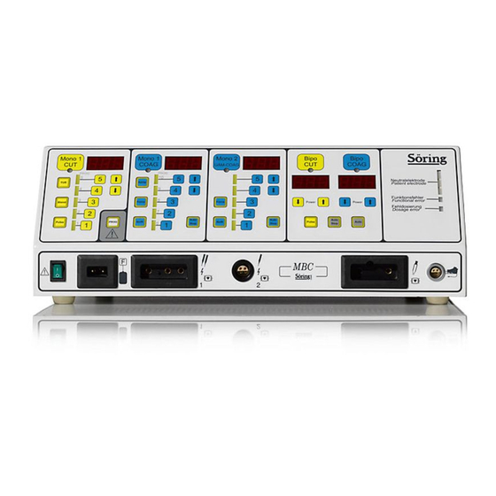
User Manuals: Söring MBC-601 HF Electrosurgical Unit
Manuals and User Guides for Söring MBC-601 HF Electrosurgical Unit. We have
2
Söring MBC-601 HF Electrosurgical Unit manuals available for free PDF download: Service Manual, User Manual
Söring MBC-601 Service Manual (89 pages)
Brand:
Söring
| Category:
Medical Equipment
| Size: 0 MB
Table of Contents
Table of Contents
3
Description of Cut-Module
4
Overview
10
General Description of the Arco-Units, MBC-Units
10
Co-Operation of Units
12
Arrangement of Modules of the Arco-3000
13
Arrangement of Modules of the Arco-2000
14
Arrangement of Modules of the Arco-1000
15
Arrangement of Modules of the Arco-1000 Table-Top
16
Arrangement of Modules of the MBC 601
17
Arrangement of Modules of the MBC 600
18
Block Diagram of Units
19
Block Diagram Primary Current Supply of the Units
20
Description of Units
21
Primary Power Supply
21
Description of Power Supply Board
21
Block Diagram Mains Board 1/2
23
Block Diagram Mains 2/2
24
Description of Microcontroller Unit, Board CPU
25
General Description
25
Connection to Other Units
25
Connection to Frontpanel
25
Connection to Handpiece Recognition Unit
25
Connection to High-Power Supply
25
Connection to Cut-Module
25
Connection to Coag-Module
25
Connection to Relay Board
25
Connection to the Mains Relay Board
26
Block Diagram CPU Board
27
Description of Front Panel
28
General Description
28
Connection to Other Units
28
Connection to CPU
28
Connection to Low-Voltage Supply
28
Block Diagram Frontpanel
29
Description of High-Power Supply
30
General Description
30
High-Power Supply, Design and Function
30
Technical Data
31
Block Diagram High Power Supply
32
Description of Cut-Module
33
General Description
33
Final Stage and Output Filter
33
Oscillator and Driver
34
Switching Stage
34
Short Circuit Switch-Off
34
Current Limiting, Current Control
34
Power Limiting
35
Arc Regulation
35
Pulse Generation and Control Logic
35
Signal Shapes
36
This Signal-Shape Is Used for the Function Cutting with Blend
36
Block Diagram Cut Module
37
Description of RF-Output Module
38
General Description
38
Description of Board HFO_A
38
Design/Function of Board HFO_A
38
Description of Board HFO_B
39
Design/Function of Board HFO_B
39
Block Diagram RF-Output Board /A
40
Block Diagram RF-Output Board /B
41
Description of Coagulator Module
42
General Description
42
Function of Coagulator Module
42
Technical Data Coagulator Module
43
Signal Shapes
43
Block Diagram Coagulation Module (Fig 8.1)
45
Description of Handpiece Recognition
46
Properties
46
Function
46
Block Diagram Handpiece Recognition Board
47
Description of Interface Board
48
Block Diagram Interfaceboard
49
Description of Gas-System
50
External Gas-System
50
Internal Gas System (Gas Control Unit and Gas Control Board)
50
General Description
50
Principle of Operation
50
Design of Gas Control Unit
50
Technical Data
50
Block Diagram Gasunit (Fig. 11.1)
51
Description of Gas Control Board
52
General Description of Gas Control Board
52
Block Diagram Gas Control Board (Fig. 11.2)
53
Service- and Adjustment Procedures
54
Description of Leds and Adjustment Potentiometers
54
Arrangement of Leds and Potentiometers I
56
Arrangement of Leds and Potentiometers II
57
Error Indication at System Start
58
Configuration of Important Bus Cables and Connectors
58
Service Mode
60
Preparation of Service Mode
60
Switching to Service Mode
60
Selecting Service Functions
61
Description of Service Functions
62
Performing Service Adjustments
62
Checking and Adjusting Basic Settings of Gas System (Service Function 0)
62
RF-Output Signal Delay Argon Coagulation (from SM 4.3 Gas Flow Adjustment) (Service Function 4)
62
Start Delay Bipolar / Resonance Frequency Bipolar Recognition
62
Adjustment of Gas Flow (Service Functions 3,7,8,9,10)
63
Adjustment of Patient Electrode Recognition (Service Function 5)
64
Auto Stop Times (Service Function 2)
64
Service Adjustments of Cut Module (Service Functions 11 and 12)
64
Calibration of Cut Module Power (Service Function 13)
65
Loudness Adjustment (Service Function 1)
65
Check of Power Measurement (Service Function 14)
65
Indication Power Supply Voltage and Current (Service Function 15)
65
Service Adjustments of the Modules
66
Adjustment of High Power Supply
66
Adjustment of Coagulator Module
66
Adjustment of Cut-Module
67
Adjustment of RF-Out B2 (SMD) [From SW 3.10]
68
Technical Data
69
Power Diagram Cutting
75
Power Diagram Blend
75
Power Diagram TUR
76
Power Diagram Pulse
76
Power Diagram TUR-Pulse
77
Power Diagram Spray-Coagulation
78
Power Diagram Force-Coagulation -Effect 1
78
Power Diagram Force-Coagulation -Effect Hi
79
Power Diagram Force-Coagulation -Effect 5
79
Power Diagram Force-Coagulation -Effect 9
80
Power Diagram Soft-Coagulation
80
Power Diagram Argon 1,6-Coagulation
81
Power Diagram Argon 2,4-Coagulation
81
Power Diagram Argon Open-Coagulation
82
Power Diagram Bipolar Cutting
83
Power Diagram Bipolar Coagulation
83
Visual and Acoustical Signals
84
Technical Checks Regarding Safety (TSC)
85
Intervals
85
Extent
85
Description of Special Checks
85
Check of Controls and Indicators
85
Check of Handpieces and Foot Switches
86
Check of RF-Generators and Safety-Devices
86
Power Measurement
86
Measurement of Gas-Flow
87
Check of Handpiece Allocation-Relay
87
Annex
88
Advertisement
Söring MBC-601 User Manual (38 pages)
Brand:
Söring
| Category:
Medical Equipment
| Size: 0 MB
Table of Contents
Table of Contents
3
1 Introduction
5
2 Important Notes Regarding the Operation of RF Surgery Units
6
Operating of RF Surgery Equipment
6
User Instructions
6
Prescribed Safety Checks
6
Medical Product Log Book
6
How to Keep the Instruction Manual and the Medical Product Log Book
7
Accident and Damage Report
7
Modifications and Repairs
7
3 Physiological and Physical Fundamentals of RF Surgery
8
Heating Effect of RF Currents in Biological Tissue
8
Reaction of Biological Tissue to Local Overheating
9
Methods of RF Surgery and Electrical Signal Shapes
12
Cutting
12
Coagulation
13
Electrodessication
13
Bipolar Application Technique
14
Bipolar Automatic
14
4 Patient Safety
15
Patient Placement
15
Attachment of Patient Electrode
15
Current Carrying Cables
18
Dangers from Inflammable and Explosive Media
19
Instructions for Special Applications
19
Arrangement of Switches, Sockets and Displays of MBC 601
20
Arrangement of Switches, Sockets and Displays of MBC 600
21
Description of Controls and Indicators
22
Description of the Safety Equipment
27
Putting the Equipment into Operation
28
Description of Operational Facilities
28
Preparation of Equipment
28
Switching on the Equipment
28
Adjustment of Function Fields
29
6 Accessories (Extracts)
30
7 Cleaning, Maintenance, Disinfection and Sterilization
31
8 Technical Data
32
9 Technical Safety Checks
35
Advertisement
Related Products
Söring MBC-600
Söring Arco-1000
Söring Arco-2000
Söring Arco-3000
Söring SONOCA 185
Söring Categories
Medical Equipment
More Söring Manuals
Login
Sign In
OR
Sign in with Facebook
Sign in with Google
Upload manual
Upload from disk
Upload from URL