Sign In
Upload
Manuals
Brands
S-Klima Manuals
Recording Equipment
CompTrol
S-Klima CompTrol Recording Equipment Manuals
Manuals and User Guides for S-Klima CompTrol Recording Equipment. We have
1
S-Klima CompTrol Recording Equipment manual available for free PDF download: Technical Manual
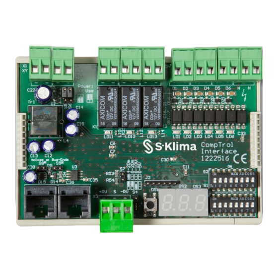
S-Klima CompTrol Technical Manual (126 pages)
Brand:
S-Klima
| Category:
Recording Equipment
| Size: 5.92 MB
Table of Contents
Table of Contents
3
About this Document
9
Scope
9
Target Group
9
Presentation Conventions
9
Abbreviations
9
Table 1: Conventions Regarding the Presentation of Safety and Warning Notes
9
Formatting
10
Nomenclature
10
Table 2: Abbreviations
10
Table 3: Formatting
10
Table 4: Nomenclature
10
Liability Claims for Defects
11
Disclaimer
11
Copyright
11
Safety Instructions
12
Proper Use
12
Safety
12
Required Personnel Qualifications
13
Compatible Products
13
Other Applicable Documents
13
Transport and Storage
14
Installation
14
Spare Parts
14
Product Package
15
Product Description
16
Comptrol Interface Connection Assignment
16
Comptrol Interface Electrical Supply
18
Pin Headers S5 and S6
18
Electrical Supply Via X/Y Remote Control Bus (Terminal X1) for a Comptrol Interface Expansion Module that Is Not in Combination with a Comptrol Master Expansion Module
18
Electrical Supply Via Terminal X5 for a Comptrol Interface Expansion Module in Combination with a Comptrol Master Expansion Module
18
Communication Connections
18
Table 5: Type of Electrical Supply
18
Digital Outputs X4A to X4C
19
Table 6: Analog Signal Type
19
Pin Headers S8 and S9
19
Digital Inputs X2A to X2N
19
Analog Input X3
19
Types of Connection
19
X/Y Remote Control Bus X1
20
Bus Connections X2 and X4
20
External Electrical Supply X5
20
DIP Switch S1
20
DIP Switch S2
21
7-Segment Display
21
Table 8: 7-Segment Display
21
Comptrol Interface Connection Diagram
22
Functions of the Comptrol Interface Expansion Module
23
Functions of Analog Input X3
23
Temperature Setpoint Definition Via Analog Signal
23
Direct Frequency Request Via an Analog Signal
23
Resistive Circuit
24
Functions Via the Digital Inputs
25
Evaluating the Analog Input
25
Table 9: Resistance Values for Voltage Dividers
25
Remote ON/OFF
26
Autoswing Function
26
Center/Center-Remote
26
Mode Selection (Cooling/Heating/Fan)
26
Preset Fan Speed
26
Special Functions
26
Automatic Fan Speed Control
26
Forced Mode
27
Inversion of Digital Outputs
27
Signal Boundary Value Monitoring
27
Table 10: Fan Speeds Dependent on Temperature Difference
27
Table 11: Signal Boundary Values for Signal Boundary Value Monitoring
27
Alarm Signal
28
Status of the Comptrol Interface (Master/Slave) in the X/Y Remote Control Bus
28
Status Signals
29
Program Overview
30
Table 7: Program Selection Via DIP Switches
30
Table 12: Program Overview
30
Configuring the Comptrol Interface for Program 0
31
Connection Diagram for Program 0
31
Description
31
Program 0 - Temperature Setpoint Definition Via Analog Signal
31
Setting Program 0 on DIP Switch S1
33
Setting the Functions for Program 0 Via DIP Switch S2
33
Setting the Analog Signal Type on S4 and S7
33
Analog Input
33
Table 13: DIP Switch Setting for Program 0
33
Table 14: Functions in Program 0
33
Table 15: Value Table for Program 0 Temperature Setpoint
34
Table 17: Digital Outputs in Program 0
35
Digital Output Assignment in Program 0
35
Table 16: Digital Inputs in Program 0
35
Digital Input Assignment in Program 0
35
Program 2 - Temperature Setpoint Definition with Window Contact Function
36
Description
36
Configuring the Comptrol Interface for Program 2
36
Connection Diagram for Program 2
36
Setting Program 2 Via DIP Switch S1
38
Setting Functions for Program 2 Via DIP Switch S2
38
Setting the Analog Signal Type on S4 and S7
38
Analog Input
38
Table 18: DIP Switch Setting for Program 2
38
Table 19: Functions in Program 2
38
Table 20: Value Table for Program 2 Temperature Setpoint
39
Window Contact Function Auto on
40
Digital Input Assignment in Program 2
40
Table 21: Digital Inputs in Program 2
40
Digital Output Assignment in Program 2
41
Table 22: Digital Outputs in Program 2
41
Program 3 - Temperature Setpoint Definition for Equipment Rooms with Temperature Limit Alarm
42
Description
42
Configuring the Comptrol Interface for Program 3
42
Connection Diagram for Program 3
42
Setting Program 3 Via DIP Switch S1
44
Setting Functions for Program 3 Via DIP Switch S2
44
Setting the Analog Signal Type on S4 and S7
44
Analog Input
44
Table 23: DIP Switch Setting for Program 3
44
Table 24: Functions in Program 3
44
Setting the Temperature Limit Value Via DIP Switch S2
45
Table 25: Value Table for Program 3 Temperature Setpoint
45
Digital Input Assignment in Program 3
46
Table 26: Setting the Temperature Limit Value
46
Table 27: Digital Inputs in Program 3
46
Table 28: Digital Outputs in Program 3
47
Digital Output Assignment in Program 3
47
Program 4 - Temperature Setpoint Definition with Hotel Remote Control Function
48
Description
48
Configuring the Comptrol Interface for Program 4
48
Connection Diagram for Program 4
48
Table 30: Functions in Program 4
50
Table 29: DIP Switch Setting for Program 4
50
Analog Input
50
Setting the Analog Signal Type on S4 and S7
50
Setting Functions for Program 4 Via DIP Switch S2
50
Setting Program 4 Via DIP Switch S1
50
Table 31: Value Table for Program 4 Temperature Setpoint
51
Digital Input Assignment in Program 4
52
Digital Output Assignment in Program 4
52
Table 32: Digital Inputs in Program 4
52
Table 33: Digital Outputs in Program 4
52
Connection Diagram for Program 5
53
Description
53
Configuring the Comptrol Interface for Program 5
53
Program 5 - Temperature Setpoint Definition With Lockout Function
53
Setting Program 5 Via DIP Switch S1
55
Table 34: DIP Switch Setting for Program 5
55
Table 35: Functions in Program 5
55
Setting Functions for Program 5 Via DIP Switch S2
55
Analog Input
55
Setting the Analog Signal Type on S4 and S7
55
Table 36: Value Table for Program 5 Temperature Setpoint
56
Digital Input Assignment in Program 5
57
Table 37: Digital Inputs in Program 5
57
Table 38: Digital Outputs in Program 5
57
Digital Output Assignment in Program 5
57
Program 6 - Temperature Setpoint Definition for Heat Exchanger Connection Module
58
Description
58
Configuring the Comptrol Interface for Program 6
58
Connection Diagram for Program 6
58
Table 39: DIP Switch Setting for Program 6
60
Table 40: Functions in Program 6
60
Setting Functions for Program 6 Via DIP Switch S2
60
Analog Input
60
Setting the Analog Signal Type on S4 and S7
60
Setting Program 6 Via DIP Switch S1
60
Digital Input Assignment in Program 6
61
Table 41: Value Table for Program 6 Temperature Setpoint
61
Digital Output Assignment in Program 6
62
Table 42: Digital Inputs in Program 6
62
Table 43: Digital Outputs in Program 6
62
Program 7 - Temperature Setpoint Definition Without Signal Boundary Value Monitoring
63
Description
63
Configuring the Comptrol Interface for Program 7
63
Connection Diagram for Program 7
63
Table 45: Functions in Program 7
65
Table 44: DIP Switch Setting for Program 7
65
Analog Input
65
Setting the Analog Signal Type on S4 and S7
65
Setting Program 7 Via DIP Switch S1
65
Setting Functions for Program 7 Via DIP Switch S2
65
Digital Input Assignment in Program 7
66
Table 46: Value Table for Program 7 Temperature Setpoint
66
Digital Output Assignment in Program 7
67
Table 47: Digital Inputs in Program 7
67
Table 48: Digital Outputs in Program 7
67
Program 8 - Direct Frequency Request
68
Description
68
Configuring the Comptrol Interface for Program 8
68
Connection Diagram for Program 8
68
For FDC Outdoor Units: Set DIP Switch S1 on the Comptrol Interface
70
Table 50: Functions in Program 8
70
Table 49: DIP Switch Setting for Program 8
70
Setting the Outdoor Unit Model Via DIP Switch S1
70
Setting the Analog Signal Type on S4 and S7
70
Setting Functions for Program 8 Via DIP Switch S2
70
Setting Program 8 Via DIP Switch S1
70
For SRC Outdoor Units: Set DIP Switch S1 on the Comptrol Interface
71
Table 51: Setting the Outdoor Unit Model with DIP Switches S1-5 to S1-8
71
Analog Input
72
Table 53: Digital Outputs in Program 8
73
Table 52: Digital Inputs in Program 8
73
Digital Output Assignment in Program 8
73
Digital Input Assignment in Program 8
73
Program 9 - Direct Frequency Request With Cascading
74
Description
74
Configuring the Comptrol Interface for Program 9
74
Connection Diagrams for Program 9
75
Comptrol Interface Connection Diagram in Program 9
75
Comptrol Interface Connection Diagram
76
Table 55: Functions in Program 9
77
Table 54: DIP Switch Setting for Program 9
77
Setting Functions for Program 9 Via DIP Switch S2
77
Setting the Analog Signal Type on S4 and S7
77
Setting Program 9 Via DIP Switch S1
77
Setting the Outdoor Unit Model Via DIP Switch S1
78
For FDC Outdoor Units: Set DIP Switch S1 on the Comptrol Interface
78
For SRC Outdoor Units: Set DIP Switch S1 on the Comptrol Interface
78
Analog Input
79
Table 56: Setting the Outdoor Unit Model with DIP Switches S1-5 to S1-8
79
Table 57: Direct Frequency Request with Cascading Without Signal Overlap - Signal Range of 1St Outdoor Unit
80
Table 58: Direct Frequency Request with Cascading with Signal Overlap - Signal of 2Nd Outdoor Unit
81
Setting the Signal Ranges Via DIP Switch S2
82
Table 59: Direct Frequency Request with Cascading with Signal Overlap - Signal Range of 1St
82
Table 60: Direct Frequency Request with Cascading with Signal Overlap - Signal of 2Nd Air
82
Table 61: Signal Overlap of 1St and 2Nd Air Conditioning Units
82
Table 63: Setting the Signal Ranges on both Comptrol Interfaces - Analog Signal
83
Table 62: Setting the Signal Ranges on both Comptrol Interfaces - Analog Signal
83
Table 64: Setting the Signal Ranges on both Comptrol Interfaces - Analog Signal
84
Table 65: Setting the Signal Ranges on both Comptrol Interfaces - Analog Signal
84
Example of Set Signal Ranges Without Signal Overlap
85
Digital Input Assignment in Program 9
85
Digital Output Assignment in Program 9
86
Table 66: Digital Inputs in Program 9
86
Table 67: Digital Outputs in Program 9
86
Program 10 - Direct Frequency Request With The Comptrol Master
87
Description
87
Configuring the Comptrol Interface for Program 10
87
Connection Diagram for Program 10
88
Connection Diagram: Connecting Comptrol Interfaces to the Comptrol Master
89
For FDC Outdoor Units: Set DIP Switch S1 on the Comptrol Interface
91
Table 68: DIP Switch Setting for Program 10
91
Table 70: Setting the Outdoor Unit Model with DIP Switches S1-5 to S1-8
91
Setting the Outdoor Unit Model Via DIP Switch S1
91
Configuring the Comptrol Master for Program 10
91
Setting Functions for Program 10 on DIP Switch S2
91
Setting Program 10 on DIP Switch S1
91
For SRC Outdoor Units: Set DIP Switch S1 on the Comptrol Interface
92
Table 69: Functions in Program 10
92
Analog Input
93
Digital Input Assignment in Program 10
93
Digital Output Assignment in Program 10
94
Table 71: Digital Outputs in Program 10
94
Installing the Comptrol Interface Expansion Module
95
General Installation Conditions
95
Service and Installation Clearance
96
Cable Requirements
96
Table 72: Cable Requirements
97
Installing and Connecting the Comptrol Interface Expansion Module
98
Initialization Sequence
100
Initialization
100
Starting up the Comptrol Interface Expansion Module
100
Troubleshooting
101
Table 73: Troubleshooting Table
103
Error Codes
104
Table 74: Comptrol Interface Error Codes
105
Rebooting the System
106
Disposal
106
Table 75: Technical Data
107
Technical Data
107
Declaration of Conformity
108
Spare Parts
109
Accessories
109
Contact
109
Manufacturer's Address
109
Table 76: Spare Parts
109
Table 77: Accessories
109
Appendix I: List of Tables
110
Appendix II: Start-Up Report
113
Advertisement
Advertisement
Related Products
S-Klima CompTrol CNT-FEA
S-Klima CompTrol CTFEA-A
S-Klima Categories
Recording Equipment
Cables and connectors
More S-Klima Manuals
Login
Sign In
OR
Sign in with Facebook
Sign in with Google
Upload manual
Upload from disk
Upload from URL