Sign In
Upload
Manuals
Brands
RVR Solar Manuals
Amplifier
VJ10000-TR
RVR Solar VJ10000-TR Manuals
Manuals and User Guides for RVR Solar VJ10000-TR. We have
1
RVR Solar VJ10000-TR manual available for free PDF download: Technical Maintenance Manual
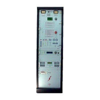
RVR Solar VJ10000-TR Technical Maintenance Manual (85 pages)
10KW Power Triode Amplifier 87.5-108 MHz
Brand:
RVR Solar
| Category:
Amplifier
| Size: 3 MB
Table of Contents
Table of Contents
3
I - Preliminary Instructions and Warranty Information
6
II - Tube Warranty Instructions
8
Varian Power Grid Product Limited Warranty
8
III - Safety Regulament
9
Warning
9
Treatmet of Electrical Shock
10
First-Aid
12
Treatment of Enectrical Burns
12
Note
12
Chapter 1
13
Vj10000-Tr General Description
13
Mechanical Description
13
Electrical Description
13
Technical Specifications
13
Chapter 2
14
Electrical Description
14
Introduction
14
Fig. 4 Hinged Frontal Panel with Telemetry
18
Fig. 5 Hinged Frontal Panel Without Telemetry
20
Fig. 6 High Voltage Panel
21
Power Supply Section
24
Chapter 3
33
Equipment Installation
33
Introduction
33
Unpacking
33
Tube Installation
35
Fig. 16 Tube Installation Diagram N°1
36
Fig. 17 Tube Installation Diagram N°2
37
Fig. 18 Tube Installation Reference View N°2
38
Fig. 19 Tube Installation Diagram N°3
39
Fig. 20 Tube Installation Reference View N°3
40
Fig. 21 Tube Installation Reference View N°4
41
Fig. 22 Tube Installation Reference View N°4
42
Equipment Setting at Work
44
Chapter 4
46
Tube Measures Card Calibration
46
Notice
46
Introduction
46
Fig. 24 Measures Card Reference View
47
Fig. 25 Measures Card Replacing Diagram N°1
48
Fig. 26 Measures Card Replacing Diagram N°2
49
Measures Card Adjusting Operations
50
Fig. 27 Power Supplies Connection for the Calibration of Test Point Voltages
53
Table D - Measure Tests Card
54
Fig. 28 Report Measure
58
Table E - Quiescent Working Parameters
59
Table F - Advisable Equipment for Test
59
Table G - Voltage Stabilyzer Parameters
59
Chapter 5
60
Maintenance
60
Safety Rules
60
Maintenance First Level
60
Maintenance Second Level
60
Modules Replacing
60
Tube Replacing
61
Air Filter Replacing
61
Appendix A
62
Circuit Diagrams and Layouts
62
Fig. 29 Power Supply Socket
63
Fig. 30 Anode Tension Transformer Socket
64
Fig. 31 Rack Power Supply Base
65
Fig. 32 High Tension Panel
66
Fig. 33 Electromechanical Plane (Triode)
67
Fig. 34 Resistenze DI Soft-Start E Polarizzazione Valvola
70
Fig. 35 Tube Amplifiers Protections Card
71
Fig. 36 High Power Relays Card
72
Fig. 37 Tuning Relays Card
73
Fig. 38 Telemetry Interface Card
74
Fig. 39 Measures Calibration Card
75
Fig. 40 Thermal Strobe Connector
76
Fig. 41 P.w.r. Measure Connector
77
Fig. 42 I2 Cbus Connector for Telemetry Box
78
Fig. 43 Ptxlcd Connector
79
Fig. 44 Low Voltage Circuit Diagram
80
Fig. 45 Three-Phases Circuit Diagram
81
Fig. 46 Measures and Allarms Circuit Diagram
82
Fig. 47 Electric Schemes
83
Chapter 6
62
Adjustments
62
Frequency Change
62
Advertisement
Advertisement
Related Products
RVR Solar VJ1000
RVR Solar Varmebaronen Viking BIO
RVR Solar PJ2000M
RVR Solar PJ5000M
RVR Solar Categories
Amplifier
Transmitter
Heater
Water Heater
Water Pump
More RVR Solar Manuals
Login
Sign In
OR
Sign in with Facebook
Sign in with Google
Upload manual
Upload from disk
Upload from URL