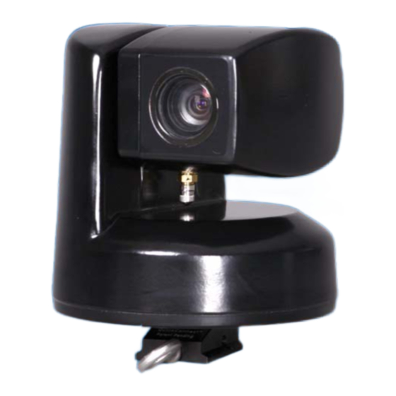
Sign In
Upload
Manuals
Brands
Rvision Manuals
Security Camera
SEE
Rvision SEE Manuals
Manuals and User Guides for Rvision SEE. We have
1
Rvision SEE manual available for free PDF download: Setup And Operation Manual
Rvision SEE Setup And Operation Manual (64 pages)
Brand:
Rvision
| Category:
Security Camera
| Size: 2 MB
Table of Contents
Table of Contents
3
Introduction
9
Figure 1: SEE™ Camera with Quickconnect Mount/Cable
10
Itar and Ear - Export Regulation Compliance
10
About this Document
10
Figure 2: Connecting the SEE™ to the SEE2PC Integration Tool
11
Connecting the SEE™ Camera to a PC
11
Figure 3: Quickconnect Mount Cable with a Thule Clamp
12
Mounting the Quickconnect Mount/Cable to a Pole
12
Mounting the Camera
13
Testing the Mount
13
Figure 4:Slide the Camera Foot into Mount Plates Shoe
13
Connecting the Hidef to Adapter to the SEE2PC
14
Integration Tool
14
Figure 5: Pull on the Eye Bolt to Insure Proper Mount
14
Figure 6: SEE2PC Integration Tool
14
Using the RS422 to RS232 Adapter
15
Figure 7: RS422 to RS232 Adapter
15
Figure 8: Serial Port Connection to a PC
15
Connecting the RS-232 Connector to a PC
15
Figure 10: Connecting the Power Cable/Plug
16
Figure 9: SEE2PC Power Cable/Plug
16
Connectors
17
Figure 11: Connector
17
Run the Cables to Controller
17
Table 1: LOOK™ Connectors Functionality
17
Connecting Power to the LOOK™ Controller
18
Figure 12: Connect Power to LOOK™ Controller
18
Figure 13: Connect Power to the DC Adapter
18
Connect the Hidef Connector to LOOK
19
Connect the LOOK™ to Power Source
19
Figure 14: Hidef Connector
19
Attach Quickconnect to Breakout Adapter
20
Connect Adapter to PC
20
Figure 15 SEE2PC Camera Integration Tool
20
Install Psee
20
Running the Psee™ Application
20
Connecting Power to the Camera
16
Connecting to the LOOK™ Controller
16
Connecting to Third Party Controllers
21
Figure 17: File Download Dialog Box
23
Controlling the SEE™ Camera with Psee™ Software
23
Installing Psee™ Software
23
Figure 18: Save as Dialog Box
24
Figure 19: Psee.zip Zipped Format
24
Figure 20: Psee™ Customer Information Dialog Box
24
Figure 21: File Download-Security Warning Dialog Box
25
Figure 22: Psee™ Program Dialog Box
25
Figure 23: Customer Information Dialog Box
26
Figure 24: Destination Folder Dialog Box
26
Figure 25: Ready to Install Program Dialog Box
27
Figure 26: Installation Progress Box
27
Table 2 : Psee™ Tabbed
28
Using the Rvision Psee™ Software
28
Figure 27: Installshield Wizard Complete Dialog Box
28
Starting the Psee™ Software
29
Figure 28: Psee™ Desktop Icon
29
Figure 29: Communication Tab Page
29
Psee™ Tabbed
30
Table 3: Communication Tab Page
30
Figure 30: Pan, Tilt, Zoom Tab Page
31
Pan, Tilt, Zoom Tab Page
31
Table 4: Pan, Tilt, Zoom Tab Page Functions
31
Figure 31: Presets Tab Page
33
Presets Tab Page
33
Storing a Preset
33
Table 5: Preset Tab Page Functions
33
Figure 32: Misc Tab Page
34
Miscellaneous (Misc) Tab Page
34
Table 6: Misc Tab Page Functions
35
Figure 33: Manual Commands Tab Page
36
Manual Commands Tab Page
36
Table 7: Manual Commands Tab Page Functions
36
Figure 34: Titling Tab Page
37
Table 8: Titling Tab Page Functions
37
Titling Tab Page
37
Figure 35: Changing Baud Rate
38
Changing the Cameras Baud Rate
38
Changing the Camera ID
38
Figure 36: Functional Elements of the LOOK
39
Joystick
40
Keypad
40
Table 10: Action on Joystick and Resulting Function
40
Table 9: LCD Status Information
40
Figure 37: LOOK™ Controller Keypad
41
LOOK™ Single Mode Overview
39
About this Document
39
Liquid Crystal Display (LCD)
39
LOOK™ Single Mode Operation
43
Table 11: LOOK™ Single Mode Keypad Functions
43
Connectors
45
Connecting the LOOK
45
Connector Cables
45
Figure 38: Connectors
45
Table 12: LOOK™ Single Mode Connectors and Their Function
45
Table 13: Cables Connected to the LOOK
45
Figure 39: Cables Connected to the LOOK
46
Appendix A - Setting up the SEE™ IP Camera
47
Changing the Camera IP Address
47
Figure 40: Control Panel
47
Figure 41: Network Connections
47
Figure 42: Connection Status
48
Figure 43: Connection Properties
48
Figure 44: Internet Protocol Properties
48
Network Communications
49
Network
49
Sensor and Alarm
49
System Connections
49
1:1 Connection
49
1:N Connection
49
Video Decoder
49
Figure 45: SEE™ IP Cable
50
Multicast Mode
50
Dns
51
Figure 46: Network Configuration
51
Local - IP Mode
51
Flow Control Mode
52
Multicast
52
Port
52
Connect SEE™IP to LAN
50
Connecting the RJ45 Connector to a PC
50
Setting up the Network Configuration
50
Serial Port Configuration - Unsupported
52
Configuring the Video
52
Encode
53
Figure 47: Video Configuration
53
Motion Detection
54
Resolution
54
Video Options and Changing Event Actions
54
Audio Configuration
54
IP Video - Logging in
55
Login ID and Password
55
Figure 48: IP Video Login
55
Table 14: SEE™IP Address, ID and Password
55
Figure 49: Live View Video Image Feed
56
Live View - Operations
56
Figure 50: Setup Link in Live View
57
Figure 51: First Window in Setup
57
Setup - Configuration
57
Figure 52: System Configuration Screen
58
General Video Functions
59
Reboot and Reset
59
Factory Reset Not Recommended
59
Time
59
SEE™ IP Configuration
58
System Configuration
58
Appendix B - Warranty and Warnings
61
Warranty and Warnings
61
Conditions of Warranty
61
Rvision Limited Warranty and Limit of Liability
62
Appendix C - Operational Specifications
63
Advertisement
Advertisement
Related Products
Rvision Categories
Refrigerator
Security Camera
Thermal cameras
More Rvision Manuals
Login
Sign In
OR
Sign in with Facebook
Sign in with Google
Upload manual
Upload from disk
Upload from URL