Sign In
Upload
Manuals
Brands
RTK Manuals
Security System
UC625 series
User Manuals: RTK UC625 series Alarm Annunciator System
Manuals and User Guides for RTK UC625 series Alarm Annunciator System. We have
1
RTK UC625 series Alarm Annunciator System manual available for free PDF download: Manual
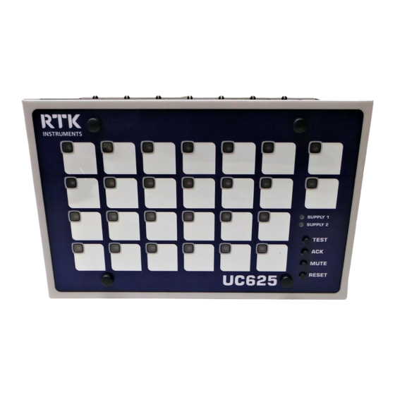
RTK UC625 series Manual (59 pages)
Compact Alarm Annunciator
Brand:
RTK
| Category:
Security System
| Size: 0 MB
Table of Contents
Important Note
2
Table of Contents
3
Figures
6
Tables
7
Introduction
9
Model Number Description
10
Option Codes
10
System Description and Features
11
General
11
Alarm Card
11
Reliable Annunciation
11
Supply/Pushbutton/Relay Card (SPR)
11
Power Failure Monitoring
11
Serviceability
12
No Special Service Tools Required
12
Inputs & Outputs
13
Customer Connections
13
Annunciator Inputs
13
Optically Coupled Inputs
13
Signal Duplicating Relays
13
Response Time
13
Common Alarm Group Relay [GP]
14
Reflash Function
14
Dual Audible Alarm Feature
14
Dual Horn Relays [HNA-HNB]
14
Dual Power Monitoring Relays
14
Mechanical Details
15
Alarm Card
15
SPR Card - Supply / Pushbutton/Relay
15
System Assembly
15
UC625 Dimensions
15
Unit Depth
15
Sequences
16
Summary
16
First-Up Sequences
16
Automatic Reset
16
Non-Latch Sequence (no Lock-In)
16
Reflash Feature
16
Ringback Sequence
17
Two Pushbutton Operation
17
Status Only Operation
17
Option M4
17
Sequence Configuration and Tables
18
Manual Reset ISA-Sequence M
18
Automatic Reset ISA-Sequence a
18
Non Lock-In Function ISA-A-4 Sequence
19
Ringback ISA-R Sequence
19
Automatic Reset First-Up ISA-F1A Sequence
20
Manual Reset First-Up ISA-F2M-1 Sequence
20
Status Only ISA-A-4-5-6 Sequence
21
Features
22
Input Configuration
22
Signal Duplicating Relays
22
Repeat Relay Mode of Operation
23
Input Follower
23
Logic Follower
23
Operation of Repeat Relays During Test
23
System Test
23
Disable Horn on System Test Option "DHT" (Model Suffix Code M1)
23
LED Indication
23
Dual Audibles and Dual Horn Relays
24
Integral Horn Disable
24
Auto-Acknowledge Feature
24
Common Alarm Relay
25
Reflash Option
25
Input Follower
26
Logic Follower
26
Sleep Mode
26
Specification
27
Optically Coupled Inputs
27
Outputs
27
Pushbuttons
28
General
28
Installation
29
Cut-Out Dimensions
29
Cabinet Fixing
29
Panel Fixing Arrangement
29
Channel Numbering
30
Connection Details
31
Typical Connection Details
31
Aux Supply Option
32
Signal Supply
33
Signal Supply Monitor Relay
33
Signal Supply Options
33
Earthing
33
Remote Pushbutton Connections
33
Optional Remote Pushbutton Connections
34
Standard Inputs Connections
35
Standard Signal Input Connections
35
Powered Inputs @ 24VDC
36
24VDC Powered Signal Input Connections
36
Higher Voltage Powered Inputs
37
48/110/250VAC/DC Powered Signal Input Connections
37
Sleep Mode
38
System DIL Switch Location and Functions
39
DIL Switch Functions on Alarm Cards
39
Identifying Card Types
40
Alarm Card Input Response Settings STANDARD VERSIONS
41
Alarm Card Input Response Settings M3 / M4 OPTION VERSIONS
42
Alarm Card Input & Sequence Settings (Set in Pairs)
43
Alarm Card DIL Switch Details (SW3 and SW5)
43
Alarm Card Relay and Horn Settings (Set in Pairs)
44
Alarm Card DIL Switch Details (SW4 and SW6)
44
DIL Switch Settings SPR Card
45
SPR Card Horn, Relay and Pushbutton Settings
46
SPR Card DIL Switch Details (SW5)
46
Automatic Acknowledge Timer (Located on SPR Card)
47
Internal Horns Disable (Located on SPR Card)
47
Maintenance
48
No Special Tools Required
48
Legend Plate Removal
48
Film Legend Engraving
48
Alarm Card or SPR Card Removal
48
Super-Bright Led's
48
Fuse Replacement
48
Signal Supply Fuse Location
49
Fuse Location for Systems Using AUX 24VDC Supply
49
Expansion Units
50
Master and Expansion UC625 Units
50
UC625 Master & Expansion Rear Terminal Views
51
UC625 Expansion Units with Ribbon Expansion Sockets
52
Options
53
Option 00 Horn Disable on System Test
53
Option 01 Lamp Test Instead of Functional Test
53
Option 02 Ringback Horn Disabled
53
Option 03 ISA R12 Sequence
53
Option 04 Response Times
53
Option 05 Lamp / Audible Test
53
Multiple Option Codes
53
Trouble Shooting Guide
54
Other RTK Products
58
Card Switch Settings Required to Set Alarm Sequences
59
Advertisement
Advertisement
Related Products
RTK
RTK 725 Series
RTK 725B Series
RTK CB10736POP1
RTK CB10736POP2
RTK CB10736POP3
RTK CB10736POP4
RTK Categories
Controller
Security System
Valve Positioners
Control Unit
Industrial Equipment
More RTK Manuals
Login
Sign In
OR
Sign in with Facebook
Sign in with Google
Upload manual
Upload from disk
Upload from URL