Sign In
Upload
Manuals
Brands
ROOTECH Manuals
Measuring Instruments
ACCURA 2500
ROOTECH ACCURA 2500 Digital Power Meter Manuals
Manuals and User Guides for ROOTECH ACCURA 2500 Digital Power Meter. We have
4
ROOTECH ACCURA 2500 Digital Power Meter manuals available for free PDF download: User Manual, Quick Start Manual
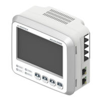
ROOTECH ACCURA 2500 User Manual (160 pages)
Smart DC Distribution Panel Digital Power Meter/Power Measuring Module
Brand:
ROOTECH
| Category:
Measuring Instruments
| Size: 10 MB
Table of Contents
Table of Contents
10
Chapter 1 Product Introduction
18
Overview
18
Fig 1.1 Identical Lengths of Accura 2550CMD and Mccbs with Various Ratings
19
Fig 1.2 Through-Hole Type Current Sensing Structure of Accura 2550CMD
19
Product Information
20
Smart DC Distribution Panel Digital Power Meter
20
Special-Purpose Module
21
Installation Example
22
Fig 1.3 Combined Installation of Accura 2500D and 2500M
22
Fig 1.4 Connection of Accura 2500D and 2500M Using Communication Cables
23
Product Features
24
Chapter 2 Installation
28
Conditions for Installation
28
Before Installation
29
Product Appearance
29
Fig 2.1 Accura 2500M Front
29
Fig 2.2 Accura 2500M Side
29
Fig 2.3 Accura 2500M Rear
29
Fig 2.5 Accura 2500M-VD Side
30
Fig 2.6 Accura 2500M-VD Rear
30
Fig 2.7 Accura 2500D Front
31
Fig 2.8 Accura 2500D Side
31
Fig 2.9 Accura 2500D Rear
31
Fig 2.10 Accura 2550CMD
32
Fig 2.11 Accura 2550DCM
33
Fig 2.12 TM-CM-1P-105
33
Fig 2.13 TM- CM-1P-60/50L/50
33
Components
34
Fig 2.15 Accura 2500M-VD Components
34
Fig 2.16 Accura 2500D Components
35
Fig 2.17 Components of Accura 2550CMD-1P-1500A Model
35
Fig 2.18 Components of Accura 2550CMD-1P-750A Model
36
Fig 2.19 Components of Accura 2550CMD-1P-250A Model
36
Fig 2.20 Components of Accura 2550CMD-1P-125A/100A/60A Model
36
Fig 2.21 Accura 2550DCM Components
37
Fig 2.22 Components of TM-CM-1P-105 Terminal Block
37
Fig 2.23 Components of TM-CM-1P-60/50L/50 Terminal Block
37
Dimensions
38
Fig 2.24 Accura 2500D/2500M Dimensions
39
Fig 2.25 Accura 2500D Dimensions
39
Fig 2.26 Accura 2550CMD-1P Dimensions
40
Fig 2.27 Accura 2550DCM Dimensions
41
Fig 2.28 TM-CM-1P Dimensions
42
Installation Example
43
Fig 2.29 Installation Diagram of Accura 2500M/ 2500D/ 2550CMD Modules
43
Step 1: Panel Mounting
44
Mounting Accura 2500D on the Panel
44
Fig 2.30 Mounting Accura 2500D on the Panel
44
Mounting Accura 2500M on the Panel
45
Fig 2.31 Mounting Accura 2500M on the Panel
45
Fig 2.32 Mounting Accura 2500M-VD on the Panel
46
Fig 2.33 Combined Installation of Accura 2500M and 2500D
47
Mounting Accura 2550CMD on the Panel
48
Fig 2.34 Mounting Accura 2550CMD on the Panel
48
Fig 2.35 Installing Accura 2550CMD-1P-1500A
49
Fig 2.36 Installing Accura 2550CMD-1P-750A through Mounting Holes (Mounting Plate/Busbar)
50
Fig 2.37 Installling Accura 2550CMD-1P through Mounting Holes (Mounting Plate/Terminal Block)
50
Installation of Accura 2550DCM
53
Fig 2.38 Panel Mounting
53
Fig 2.39 DIN Rail Mounting
53
Step 2: Wiring Accura 2500M Module
54
Voltage Wiring of Accura 2500M
54
Fig 2.38 Voltage Wiring of Accura 2500M
54
Fig 2.41 1DC2W Connection
55
Fig 2.42 2DC3W Connection
55
Fig 2.43 3DC4W Connection
56
Fig 2.44 Bipolar(3W) Connection
56
Voltage Wiring of Accura 2500M-VD
57
Fig 2.45 DC Voltage Connection of Accura 2500M-VD
57
Fig 2.46 1DC2W Connection of Accura 2500M-VD
58
Fig 2.47 Bipolar(3W) Connection of Accura 2500M-VD
58
Control Power Supply /Ground Wiring
59
Fig 2.48 Unipolar(2W) Connection of Accura 2500M-VD
59
Fig 2.49 Control Power Supply Wiring of Accura 2500M
59
Step 3: Connecting Accura 2500M with 2500D Via the Communication Cable
61
Fig 2.50 DISPLAY Port on Accura 2500M
61
Fig 2.51 Accura 2500D Rear
61
Fig 2.52 Connecting Accura 2500M with 2500D Using the Communication Cable
62
Step 4A: Current Wiring of Accura 2550CMD Module
63
Direct Connection to Accura 2550CMD-1P Module
63
Fig 2.53 Wiring of Accura 2550CMD-1P-1500A Module
63
Fig 2.54 Wiring of Accura 2550CMD-1P-750A Module
64
Through-Hole Wiring of Accura 2550CMD-1P Module
65
Fig 2.55 Through-Hole Wiring of Accura 2550CMD-1P-250A Module
65
Fig 2.56 Through-Hole Wiring of Accura 2550CMD-1P-125A/100A/60A Module
65
Step 4B: Voltage/Current Wiring of Accura 2550DCM
66
Fig 2.57 Wiring of Accura 2550DCM
66
Step 5: Connecting Accura 2500M with 2550 Modules
67
Fig 2.58 Connection between Accura 2500M/2550 Modules Using Internal Communication Cables
68
Step 6: Connecting Accura 2500M Modules for External Communication
69
Ethernet Communication
69
Fig 2.59 Ethernet Ports on Accura 2500M
69
Fig 2.60 Connecting Accura 2500M Modules Via Ethernet Communication
70
RS-485 Communication
71
Fig 2.61 RS-485 Port on Accura 2500M
71
Fig 2.62 Connecting Accura 2500M Modules Via RS-485 Communication
71
Chapter 3 Accura 2500M
72
Device Composition
72
Fig 3.1 Device Composition of Accura 2500M
72
Control Power Supply
73
Fig 3.2 Control Power Supply of Accura 2500M
73
Voltage Terminal Block
74
Fig 3.3 Voltage Wiring of Accura 2500M
74
Fig 3.4 Voltage Wiring of Acura 2500M-VD
75
Ethernet Port for External Communication
76
Fig 3.5 Ethernet Ports on Accura 2500M
76
Fig 3.6 Connecting Accura 2500M Modules with Ethernet Cables for External Communication
77
(Daisy-Chain & Ring Topology)
77
RS-485 Port for External Communication
78
Fig 3.7 RS-485 Port on Accura 2500M
78
Fig 3.8 Connecting Accura 2500M Modules with the RS-485 Cable for External Communication
78
Communication Port for Connection with the HMI DISPLAY Module
79
Fig 3.9 Combined Connection between Accura 2500M and Accura 2500D
79
Fig 3.10 Connecting Accura 2500M with Accura 2500D Using the Communication Cable
79
Communication Ports for Connection with Accura 2550 Modules
80
Fig 3.11 Connection Example of Accura 2500 and Accura 2550 Modules
80
LED Status Indicators
81
Functions
82
External Communication with the Host System
82
Measurements
82
Power Quality
83
Events
83
Fig 3.12 Block Diagram of Custom Events
84
Controls of Accura 2550 Modules
85
Accura 2500D Interface
85
Chapter 4 Accura 2500D
86
Device Composition
86
Fig 4.1 Accura 2500D Device Composition
86
Connection
88
Fig 4.2 Combined Connection with Accura 2500M
88
Fig 4.3 Connection with Accura 2500M Using the Communication Cable
88
DISPLAY (HOME) Mode
89
Screen Composition
89
Display Screen of Accura 2550CMD Module
90
Fig 4.4 SUMMARY Measurement Screen
90
Fig 4.5 DC Voltage Measurement Screen
91
Fig 4.6 Current Measurement Screen
91
Fig 4.7 DC Power Measurement Screen
92
Fig 4.8 DC Energy Measurement Screen
92
Fig 4.9 Waveform Measurement Screen
93
Fig 4.10 Description Screen
93
Display Screen of Accura 2550DCM Meter
94
Fig 4.11 DO(Digital Output) Information Screen
94
SETUP Mode
95
Screen Composition
95
Accura 2500M Setup
95
Fig 4.12 SUMMARY Setup Screen
96
Fig 4.13 Voltage Measurement Setup Screen
96
Fig 4.14 Changed Item Displayed
97
Fig 4.15 Dip Event Setup Screen
97
Fig 4.16 Ethernet Communication Setup Screen
98
Fig 4.17 Main CMD Setup Screen
99
Fig 4.18 Reset Screen
99
Fig 4.19 Description Setup Screen
100
Accura 2550CMD Setup
102
Fig 4.20 SUMMARY Setup Screen
102
Fig 4.21 Current Measurement Setup Screen
102
Fig 4.22 Current Event Setup Screen
103
Fig 4.23 DC Adjustment Setup Screen
104
Fig 4.24 Description Setup Screen
104
Accura 2550DCM Setup
105
Fig 4.25 SUMMARY Setup Screen
105
Fig 4.26 Voltage Measurement Setup Screen
105
Fig 4.27 Voltage Event Setup Screen
106
Fig 4.28 DO Setup Screen
107
Fig 4.29 DC Adjustment Setup Screen
108
Fig 4.30 Description Screen
108
EVENT Mode
109
Screen Composition
109
Measurement Events
110
Fig 4.31 SUMMARY Event Screen
110
Fig 4.32 Measurement Event Screen
110
Power Quality Events
111
Fig 4.33 RMS/DC Trend Screen
111
Fig 4.34 Power Quality Event Screen
111
SYSTEM Events
112
Fig 4.35 RMS/DC Trend Screen
112
Fig 4.36 SYSTEM Events Screen
112
Necessary Steps for Device Setup
113
Step 1: Setup for the Measured Voltage Type of Accura 2500M
113
Step 2: Voltage Wiring and Reference Voltage Setup of Accura 2500M
113
Step 3: Module ID Setup of Accura 2550 Modules
113
Step 4: Ethernet Setup of Accura 2500M
113
Chapter 5 Accura 2550
114
Operation Mode
114
Button Operation
114
Accura 2550CMD
115
Applied Models
115
LCD Display
115
Display Mode
116
Setup Mode
117
Accura 2550DCM
120
Applied Models
120
LCD Display
120
Display Mode
121
Setup Mode
122
Chapter 6 Functions
125
Voltage/Current Sampling
125
Voltage Sensing
125
Current Sensing
125
Fig 6.1 Voltage Sensing and Signal Processing
125
Fig 6.2 Current Sensing and Signal Processing
125
Voltage and Current Sensing of Accura 2550DCM
126
Measuring Time
126
Calculation Per Subframe
126
Fig 6.3 Voltage and Current Sensing and Signal Processing
126
Measurements
127
Measurement Parameters
127
Voltage Wiring
128
Fig 6.4 DC Voltage Wiring with a Single Wire (1DC2W)
128
Fig 6.5 DC Voltage Wiring with 2 Wires and a Common Ground Wire (2DC3W)
129
Fig 6.6 DC Voltage Wiring with 3 Wires and a Common Ground Wire (3DC4W)
130
Fig 6.7 Bipolar DC Voltage Wiring with a Common Ground Wire
131
Fig 6.8 Unipolar DC Voltage Wiring
132
Power
133
Energy
133
Capacitance Estimation
134
Fig 6.9 Equivalent Circuit of a Capacitor
134
Events
136
Power Quality Events
136
Fig 6.10 Voltage Dip Detection
136
Measurement Events
137
Fig 6.10 Block Diagram of Custom Events
138
Fig 6.12 「Over」 Condition Detection
139
Fig 6.13 「Under」 Condition Detection
139
System Events
140
Providing Event Notifications and Resetting Notification Settings
140
Aggregation
142
Fixed Aggregation
142
Fig 6.14 Aggregation Process
142
Custom Aggregation
143
Collection of Aggregated Data
143
Appendix A Specifications
144
General Specifications
144
Accura 2500M Main Distribution Panel Module
144
Accura 2500D Main Distribution Panel HMI Module
147
Accura 2550CMD-1P DC Power Measuring Module
148
Accura 2550DCM DC Power Measuring Meter
150
Appendix B Module Connection
152
Limitation in the Length of the Communication Cable Due to Voltage Drops
152
Limitation in the Number of Connectable Modules Due to Power Consumption
153
Limitation in the Number of Connectable Modules in a Single Group
153
Fig B.1 Module Connection Diagram in a Single Group
154
Connecting Modules in Two Groups
155
Fig B.2 Module Connection Diagram in Two Groups
155
Appendix C Standards
156
Appendix D Accuracy/Reliability
157
Accuracy
157
Reliability
158
Appendix E Ordering Information
159
Accura 2500/2550 Smart DC Distribution Panel Digital Power Meter
159
Special-Purpose Modules
159
Advertisement
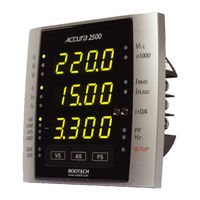
ROOTECH ACCURA 2500 User Manual (46 pages)
High Accuracy Digital Power Meter
Brand:
ROOTECH
| Category:
Measuring Instruments
| Size: 1 MB
Table of Contents
Table of Contents
9
Chapter 1 Introduction
12
Overview
12
Power Measurements
12
Accuracy
12
CE/UL Safety and Reliability
12
Display Easy to Read
12
Communication[Irda]
12
Fig 1.1 Accura PDA Software
13
Features
14
Measurement
14
Irda Communication
14
Communication
14
Power Supply
14
Applications
15
True RMS Measurements Robust to Harmonics
15
Power Quality Using PDA
15
Compatibility with Analog Meters
15
Parameters
16
Chapter 2 Mounting
17
Environmental Conditions
17
Enclosure Considerations
17
Before You Begin
18
Meter Overview
18
Fig 2.1 Front Side
18
Meter Dimensions
19
Fig 2.3 Front View
19
Fig 2.5 Side View
19
Step 1: Mounting
20
Sequence
20
Fig 2.6 ANSI 4
20
Step 2: Voltage and Current Inputs
21
Voltage Input
21
Fig 2.8 Voltage and Current Connector
21
Current Input
22
Wiring Diagram Using External Pts
23
Fig 2.9 Single Phase 2 Wires, Wiring Mode = 1P2U
23
Fig 2.10 Three Phase 3 Wire Open Delta Using 2Cts, Wiring Mode = 3P3O
24
Fig 2.11 Three Phase 3 Wire Open Delta Using 3Cts, Wiring Mode = 3P3O
24
Fig 2.12 Three Phase 4 Wires Using 3 Pts and 3 Cts, Wiring Mode = 3P4U
25
Direct Diagram Using no Pts
26
Fig 2.13 Single Phase 2 Wire Direct , Wiring Mode = 1P2U
26
Fig 2.14 Single Phase 3 Wire Direct Using 2 Cts, Wiring Mode = 1P3U
27
Fig 2.15 Three Phase 3 Wire Open Delta Direct, Wiring Mode = 3P3O
27
Fig 2.16 Three Phase 3 Wire Open Delta Direct Using 3 Cts, Wiring Mode = 3P3O
28
Fig 2.17 Three Phase 4 Wire Direct Using 3 Cts, Wiring Mode = 3P4U
28
Step 3: Wire the Power Supply and Ground Terminal
29
Power Supply
29
Ground Terminal
29
Fig 2.18 Wiring of Power Supply and Ground Terminal
29
Step 4: Add a Cover/Power up the Meter
30
Add a Cover
30
Power up the Meter
30
Fig 2.19 Cover
30
Chapter 3 Meter Operation/Setup
31
Display Mode
31
Fig 3.1 Measurement Groups
31
Setup Mode
35
Reset Mode
36
System Mode
37
Reactive Calculation Method
38
Fig 3.2 P , Q[According to General Calculation]
38
APPENDIX A Standard Specification
40
APPENDIX B Standard Compliance
41
APPENDIX C Test Report
42
Measurement Test
42
Reliability Test
43
Index
44
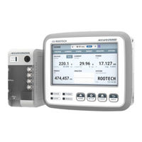
ROOTECH ACCURA 2500 User Manual (32 pages)
Mixed Power Voltage Measuring Module
Brand:
ROOTECH
| Category:
Measuring Instruments
| Size: 1 MB
Table of Contents
Table of Contents
7
Chapter 1 Installation and Wiring
9
Product Appearance
9
Components
9
Fig 1.1 Accura 2550VOL
9
Fig 1.2 Accura 2550VOL Components
9
Dimensions
10
Fig 1.3 Accura 2550VOL Dimensions
10
Installation Example
11
Fig 1.4 Accura 2500/2550VOL Installation Diagram
11
Step 1: Installing Accura 2550VOL
12
Panel Mounting
12
Fig 1.5 Mounting Accura 2550VOL on the Panel
12
DIN Rail Mounting
13
Fig 1.6 Mounting Accura 2550VOL on the DIN Rail
13
Step 2: Connecting Accura 2550VOL with Accura 2500M/2550CM[Z]
14
Connection for Internal Communication
14
Fig 1.7 Connection between Accura 2500M and Accura 2550VOL Using the Communication Cable
14
Chapter 2 Accura 2550VOL Operation and Setup
15
Device Configuration
15
Fig 2.1 Accura 2550VOL Device Configuration
15
Power Supply
16
ID Setup
16
LED Status Indicators
16
Communication Ports for Connection with Accura 2500M/2550VOL
17
Chapter 3 Accura 2500D Operation and Setup
18
DISPLAY(HOME) Mode
19
Fig 3.4 Active Power Measurement Screen
21
Fig 3.7 Description Screen
23
SETUP Mode
24
Fig 3.10 Changed Item Displayed
25
Fig 3.11 Description Setup Screen
26
Appendix A Specifications
27
Accura 2550VOL Mixed Power Voltage Measuring Module
27
Appendix B Accuracy/Power Quality
29
Accuracy
29
Accuracy of Power Quality Data
30
Appendix C Ordering Information
31
Advertisement
ROOTECH ACCURA 2500 Quick Start Manual (16 pages)
Brand:
ROOTECH
| Category:
Measuring Instruments
| Size: 17 MB
Table of Contents
Setup Procedure
2
Setup Mode
3
Setup Menu
4
Rated Current
5
Button Operation
9
Advertisement
Related Products
ROOTECH ACCURA 2500D
ROOTECH Accura 2550
ROOTECH ACCURA 2550CMD-1P-250A
ROOTECH ACCURA 2550CMD-1P-125A
ROOTECH ACCURA 2550CMD-1P-60A
ROOTECH ACCURA 2550DCM-50V-80A
ROOTECH ACCURA 2550GW
ROOTECH ACCURA 2550VOL
ROOTECH ACCURA 2550CMD-1P-750A
ROOTECH ACCURA 2550CMD-1P-1500A
ROOTECH Categories
Measuring Instruments
I/O Systems
Relays
Control Unit
Thermostat
More ROOTECH Manuals
Login
Sign In
OR
Sign in with Facebook
Sign in with Google
Upload manual
Upload from disk
Upload from URL