Sign In
Upload
Manuals
Brands
ROOTECH Manuals
Measuring Instruments
ACCURA 2350-TEMPS
ROOTECH ACCURA 2350-TEMPS Manuals
Manuals and User Guides for ROOTECH ACCURA 2350-TEMPS. We have
3
ROOTECH ACCURA 2350-TEMPS manuals available for free PDF download: User Manual
ROOTECH ACCURA 2350-TEMPS User Manual (252 pages)
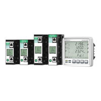
Digital Power Meter/ Power Measuring Module
Brand:
ROOTECH
| Category:
Measuring Instruments
| Size: 17 MB
Table of Contents
Table of Contents
10
Chapter 1 Introduction
18
Overview
18
Fig 1.1 Through-Hole Type Current Sensing Structure of Accura 2350-3P/1P Module
19
Fig 1.2 Accura 2350 Module Compatible with Mccbs/Elbs with Various Ratings
20
Fig 1.3 Installation of Accura 2350-3PSC/1PSC Module
20
Applications
21
Product Information
22
Digital Meter/Power Measuring Module
22
Special-Purpose Modules
24
Installation Example
25
Fig 1.4 Installation Example of Accura 2300S/2350 Modules
25
Fig 1.5 Installation Example of Split-Core Power Measuring Module
26
Product Features
27
Chapter 2 Installation
32
Installation Conditions
32
Before Installation
33
Product Appearance
33
Fig 2.1 Accura 2300S Front
33
Fig 2.3 Accura 2300S Rear
33
Fig 2.5 Accura 2350-3PSC/1PSC/1PSCSH Split-Core Power Measuring Modules
34
Components
35
Fig 2.6 Accura 2300S Components
35
Fig 2.7 Accura 2350-3P Components
35
Fig 2.8 Accura 2350-1P Components
35
Fig 2.9 Accura 2350-1PSH Components
36
Fig 2.10 Accura 2350-3PSC Components
36
Fig 2.11 Accura 2350-1PSC Components
36
Fig 2.12 Accura 2350-1PSCSH Components
37
Fig 2.13 TM-3P Components
37
Fig 2.14 TM-1P Components
37
Dimensions
38
Fig 2.15 Accura 2300S Front Dimensions
38
Fig 2.17 Accura 2300S Rear Dimensions
38
Fig 2.18 Accura 2350-3P Module Dimensions
39
Fig 2.19 TM-3P Terminal Block Dimensions
39
Fig 2.20 Accura 2350-1P Module Dimensions
40
Fig 2.22 Accura 2350-1PSH Module Dimensions
40
Fig 2.21 TM-1P Single-Phase Terminal Block Dimensions
41
Fig 2.23 Accura 2350-3PSC Module Dimensions
42
Fig 2.24 Accura 2350-1PSC Module Dimensions
43
Fig 2.25 Accura 2350-1PSCSH Module Dimensions
43
Installation Example
45
Fig 2.26 Installation Diagram of Accura 2300S/2350-3P/1P Power Measuring Modules
45
Fig 2.27 Installation Diagram of Accura 2300S/2350 Split-Core Power Measuring Modules
46
Step 1: Installing the Product
47
Mounting Accura 2300S on the Panel
47
Fig 2.28 Mounting Accura 2300S on the Panel
47
Mounting Accura 2350-3P Power Measuring Modules on the Panel
48
Fig 2.29 Mounting Accura 2350-3P Module on the Panel
48
Fig 2.30 Mounting Accura 2350-3P Module on the Panel through Mounting Holes
49
Fig 2.31 Mounting the Mounting Plate / Terminal Block for Accura 2350-3P on the Panel
53
Mounting Accura 2350-1P Power Measuring Module on the Panel
55
Fig 2.32 Mounting Accura 2350-1P Module on the Panel(Load Located on the Right Side)
55
Fig 2.33 Mounting Accura 2350-1P Module on the Panel through Mounting Holes
56
Fig 2.34 Mounting the Mounting Plate / Terminal Block for Accura 2350-1P on the Panel
60
Mounting Accura 2350-3PSC Power Measuring Module on the Panel
62
Fig 2.35 Mounting Accura 2350-3PSC Module on the Panel (New Installation)
62
Fig 2.36 Mounting Accura 2350-3PSC Module on the Panel through Mounting Holes
63
Fig 2.37 Mounting the Mounting Plate for Accura 2350-3PSC Module on the Panel
65
Fig 2.38 Mounting Accura 2350-3PSC Module on the Panel (Retrofit Installation)
66
Mounting Accura 2350-1PSC Power Measuring Module on the Panel
67
Fig 2.39 Mounting Accura 2350-1PSC Module on the Panel (New Installation)
67
Fig 2.40 Mounting Accura 2350-1PSC Module on the Panel through Mounting Holes
68
Fig 2.41 Mounting the Mounting Plate for Accura 2350-1PSC Module on the Panel
70
Fig 2.42 Mounting Accura 2350-1PSC Module on the Panel (Retrofit Installation)
71
Mounting Accura 2350-1PSCSH Power Measuring Module on the Panel
72
Fig 2.43 Mounting Accura 2350-1PSCSH Module on the Panel (New Installation)
72
Fig 2.44 Mounting Accura 2350-1PSCSH Module on the Panel through Mounting Holes
73
Fig 2.45 Mounting the Mounting Plate for Accura 2350-1PSCSH Module on the Panel
74
Fig 2.46 Mounting Accura 2350-1PSCSH Module on the Panel (Retrofit Installation)
75
Step 2: Wiring Accura 2300S
76
Voltage Wiring of Accura 2300S
76
Fig 2.47 Voltage Wiring of Accura 2300S
76
Fig 2.48 3-Phase 4-Wire, Direct Connection
78
Fig 2.49 3-Phase 4-Wire Connection with 3 Pts
78
Fig 2.50 3-Phase 3-Wire, Direct Connection
79
Fig 2.51 3-Phase 3-Wire Connection with 2 Pts
79
Fig 2.52 1-Phase 3-Wire, Direct Connection
80
Fig 2.53 1-Phase 3-Wire Connection with 2 Pts
80
Fig 2.54 1-Phase 2-Wire, Direct Connection
81
Fig 2.55 1-Phase 2-Wire Connection with 1 PT
81
Digital Input/Output Wiring of Accura 2300S
82
Fig 2.56 Digital Input/Output Channels on Accura 2300S
82
Fig 2.57 Digital Inputs
82
Fig 2.58 Application of DC Relay
84
Fig 2.59 Application of AC Relay
84
Step 3: Through-Hole Current Wiring of Accura 2350
85
Through-Hole Wiring of Accura 2350-3P/3PSC Modules
85
Fig 2.60 3P4W/3P3W Through-Hole Wiring
86
Fig 2.61 3P4W/3P3W Through-Hole Wiring with 3 Cts
86
Fig 2.62 3P3W Through-Hole Wiring with 2 Cts
87
Through-Hole Wiring of Accura 2350-1P/1PSH/1PSC Modules
89
Fig 2.64 Single-Phase Line-To-Neutral Through-Hole Wiring
90
Fig 2.65 Single-Phase Line-To-Line Through-Hole Wiring
90
Through-Hole Wiring of Accura 2350-1PSCSH Modules
91
Fig 2.66 Grouping Three Accura 2350-1PSCSH Modules in 3P4W/3P3W Mode
92
Fig 2.67 Grouping Two Accura 2350-1PSCSH Modules in 3P3W Mode
92
Fig 2.68 Single-Phase Line-To-Neutral Through-Hole Wiring of Single-Hole Module
93
Fig 2.69 Single-Phase Line-To-Line Through-Hole Wiring of Single-Hole Module
93
Step 4: Connecting Accura 2350 with External Zcts
94
Fig 2.70 Connecting the Cable for Connection with the ZCT to the External ZCT
94
Fig 2.71 Connecting Accura 2350 Module to the External ZCT
94
Step 5: Connecting Accura 2300S to Accura 2350
95
Fig 2.72 Example of Connecting Accura 2300S to Accura 2350 for Dedicated Communication
95
Step 6: Connecting Accura 2300S Devices for External Communication
97
Ethernet Communication
97
Fig 2.73 Ethernet Communication Ports on Accura 2300S
97
Fig 2.74 Connecting Accura 2300S Devices Via Ethernet Communication
98
RS-485 Communication
99
Fig 2.75 RS-485 Communication Port on Accura 2300S
99
Fig 2.76 Connecting Accura 2300S Devices Via RS-485 Communication
99
Step 7: Accura 2300S Power Supply and Ground Wiring
100
Power Supply Wiring
100
Ground Wiring
100
Fig 2.77 Accura 2300S Power Supply Wiring
100
Chapter 3 Accura 2350 Operation/Setup
101
Operation Mode
101
Button Operation
101
Accura 2350-3P/3PSC
102
Applied Model
102
Front View
102
Display Mode
103
Setup Mode
105
Accura 2350-1P/1PSC
119
Applied Model
119
Front View
119
Display Mode
120
Setup Mode
120
Accura 2350-1PSCSH
129
Applied Model
129
Front View
129
Display Mode
130
Setup Mode
130
Chapter 4 Accura 2300S Operation/Setup
141
Device Configuration
141
Operation Modes
141
LED Display
141
Fig 4.1 Accura 2300S Front View
141
Button Operation
142
Fig 4.2 Screen in Display Mode
142
Fig 4.3 Screen in Setup Mode
142
Fig 4.4 Screen in Event Mode
143
Display Mode
144
Front View
144
Fig 4.5 Accura 2300S Front View
144
Fig 4.6 Temperature Sensor on Accura 2300S
145
Selecting the ID of Accura 2350 Module
146
Fig 4.7 Selecting the ID of Accura 2350 Module
146
Full Display Screen
148
Measurement of Voltage/Current/Power/Energy
149
Fig 4.8 Voltage/Current/Power/Energy Display Screen
149
Fig 4.9 Voltage/Current/Power/Energy Display Screen for each Phase
149
Measurement of Voltage/Frequency
150
Measurement of Current
150
Fig 4.10 Line-To-Line Voltage Display Screen
150
Fig 4.11 Phase Current Display Screen
150
Measurement of Power/Power Factor
151
Measurement of Demand
151
Fig 4.12 Active Power Display Screen
151
Fig 4.13 Active Power Demand Display Screen
151
Measurement of Active Energy
152
Measurement of Leakage Current
152
Fig 4.14 Net Energy Display Screen
152
Fig 4.15 Leakage Current Display Screen
152
Ethernet Information
153
Fig 4.16 Ethernet Connection Status Display Screen
153
Temperature/Date & Time
154
Fig 4.17 Temperature Display Screen
154
Setup Mode
155
Full Screen in Setup Mode
156
Measurement Setup
157
Fig 4.18 3-Phase 4-Wire Connection(3P4W): Setup for PT Primary V
157
Secondary V Values
157
Fig 4.19 3-Phase 3-Wire Connection(3P3W): Setup for PT Primary V
158
Secondary
158
Fig 4.20 1-Phase 3-Wire Connection(1P3W): Setup for PT Primary V
158
Fig 4.21 1-Phase 2-Wire Connection(1P2W): Setup for PT Primary V
158
Event Setup
163
Fig 4.22 Dip Event Setup(3-Phase 4-Wire)
164
Fig 4.23 Dip Event Setup(3-Phase 3-Wire)
164
Fig 4.24 Swell Event Setup(3-Phase 4-Wire)
166
Fig 4.25 Swell Event Setup(3-Phase 3-Wire)
166
Accura 2350 Module ID Setup
173
Accura 2350-1P Device Group Setup
177
Ethernet Communication Setup
180
RS-485 Communication Setup
183
Reset Configuration
185
Digital Input/Output Setup
187
Display Setup
192
Information
195
Event Mode
196
Start Event and End Event
196
Providing Notifications for Start Events
196
Clearing Event Notifications
196
Fig 4.26 Dip(Sag) Event Notification Screen
196
Fig 4.27 Swell Event Notification Screen
196
Button Function
197
Event Log Number
198
Event Timestamp
198
Fig 4.28 Example of Event Log Number
198
Dip Event Log
199
Swell Event Log
199
Fuse Fail Event Log
200
Temperature Event Log
201
Current Event Log
201
Leakage Current Event Log
202
Demand Current Event Log
203
Power Event Log
204
No Event Log
204
Necessary Steps for Device Setup
205
Step 1: Setup for the Voltage Wiring of Accura 2300S and PT Rating
205
Step 2: Automatic Assignment of Accura 2350 Module Ids and Update of Ids
206
Step 3: Ethernet Setup of Accura 2300S
209
Chapter 5 Measurements
210
Measurement Parameters
210
Measurement Events
212
User-Defined Events
213
Fig 5.1 Block Diagram of User-Defined Events
213
Voltage Wiring
214
3-Phase 4-Wire Connection
214
Fig 5.2 3P4W Connection with 3 Pts and 3 Cts
214
3-Phase 3-Wire Connection
215
Fig 5.3 3P3W Connection with 2 Pts and 3 Cts
215
1-Phase 3-Wire Connection
217
Fig 5.4 1P3W Connection with 2 Pts and 2 Cts
217
1-Phase 2-Wire Connection
218
Fig 5.5 1P2W Connection with 1 PT and 1 CT
218
Measurement of Voltage Dips(Sags)/Swells
219
Fig 5.6 Calculation of 1-Cycle RMS Voltage Refreshed each Half Cycle
219
Fig 5.7 Voltage Dip(Sag) Detection
219
Leakage Current Measurement
220
Residual Voltage Measurement
220
Residual Current Measurement
220
Measurement of Power Per Phase
221
Three-Phase Power Measurement
222
Fig 5.8 Vector Sum for the Total Apparent Power
222
Power Factor(PF) Measurement
223
Fig 5.9 Arithmetic Sum for the Total Apparent Power
223
Phase Angle Measurement(Lead/Lag)
224
Fig 5.10 PF Sign and Phase Angle(Lead/Lag)
224
Demand Measurement
225
Fig 5.11 Demand Calculation
225
Fig 5.12 Predicted Demand Calculation
225
Fig 5.13 Hourly Auto Sync
226
Fig 5.14 Manual Sync
226
Voltage Harmonics
227
Current Harmonics
227
Unbalance(Nema MG1)
227
Negative-Sequence/Zero-Sequence Unbalance
229
Fig 5.15 Symmetrical Components
229
Aggregation
230
Fig 5.16 Aggregation Process for Avg/Max/Min Values
230
Fig 5.17 Aggregation Process for the Last Latched Values
230
Appendix A Specifications
233
Appendix B Standards
243
IEC 61557-12:2018 Performance Measuring and Monitoring Devices(PMD)
244
IEC 62053-22:2020 Static Meters for AC Active Energy (Classes 0.1S, 0.2S and 0.5S)
246
IEC 62053-24:2020 Static Meters for Fundamental Reactive Energy (Classes 0.5S, 1S, 1, 2 and 3)
246
Appendix C Accuracy/Reliability
247
Accuracy
247
Reliability
248
Appendix D Line-To-Neutral Voltage for Common Main Supply Systems
249
Wiring Modes
249
Appendix E Ordering Information
250
Advertisement
ROOTECH ACCURA 2350-TEMPS User Manual (174 pages)
Digital Power Meter/ Single-Phase Three-Feeder Power Measuring Module
Brand:
ROOTECH
| Category:
Measuring Instruments
| Size: 14 MB
Table of Contents
Table of Contents
8
Chapter 1 Introduction
15
Overview
15
Fig 1.1 Accura 2350-1P3FSC Module Compatible with Mccbs/Elbs
17
Fig 1.2 Installation of Accura 2350-1P3FSC Module
17
Applications
18
Product Information
19
Digital Meter/Split-Core Single-Phase Three-Feeder Power Measuring Module
19
Digital Power Meter / General Power Measuring Module
20
Special-Purpose Modules
20
Installation Example
21
Fig 1.3 Installation of Accura 2350-1P3FSC (Using Accura 2350-3P-CT5A Module)
21
Fig 1.4 Installation of Accura 2350-1P3FSC (Using Accura 2350-1PSCSH Modules)
22
Product Features
23
Chapter 2 Installation
26
Installation Conditions
26
Before Installation
27
Product Appearance
27
Fig 2.1 Accura 2300S Front
27
Fig 2.3 Accura 2300S Rear
27
Components
28
Fig 2.4 Accura 2350-1P3FSC Power Measuring Modules
28
Fig 2.5 Accura 2300S Components
28
Fig 2.6 Accura 2350-1P3FSC Components
28
Dimensions
29
Fig 2.7 Accura 2300S Front Dimensions
29
Fig 2.9 Accura 2300S Rear Dimensions
29
Fig 2.10 Accura 2350-1P3FSC Module Dimensions
30
Installation Diagram
31
Fig 2.11 Installation Diagram of Accura 2350-1P3FSC (Using Accura 2350-3P-CT5A Module)
31
Fig 2.12 Accura 2350-1P3FSC Installation Diagram (Using Accura 2350-1PSCSH Module)
32
Step 1: Installing the Product
33
Mounting Accura 2300S on the Panel
33
Fig 2.13 Mounting Accura 2300S on the Panel
33
Mounting Accura 2350-1P3FSC Power Measuring Module on the Panel
34
Fig 2.14 New Installation of Accura 2350-1P3FSC (Using Mounting Wings)
34
Fig 2.15 Mounting Accura 2350-1P3FSC on the Panel through Mounting Holes
35
Fig 2.16 New Installation of Accura 2350-1P3FSC (Using the Lower Part of the Module)
36
Fig 2.17 Retrofit Installation of Accura 2350-1P3FSC (Securing the Module with Cable Ties)
37
Fig 2.18 Retrofit Installation of Accura 2350-1P3FSC
38
Step 2: Accura 2300S Wiring
39
Accura 2300S Voltage Wiring
39
Fig 2.19 Voltage Wiring of Accura 2300 S
39
Fig 2.20 3-Phase 4-Wire, Direct Connection
41
Fig 2.21 3-Phase 4-Wire Connection with 3 Pts
41
Fig 2.22 3-Phase 3-Wire, Direct Connection
42
Fig 2.23 Three-Phase 3-Wire Connection with 2 Pts
42
Fig 2.24 Single-Phase 3-Wire, Direct Connection
43
Fig 2.25 1-Phase 3-Wire Connection with 2 Pts
43
Fig 2.26 1-Phase 2-Wire, Direct Connection
44
Fig 2.27 1-Phase 2-Wire Connection with 1 PT
44
Digital Input/Output Wiring of Accura 2300S
45
Fig 2.28 Digital Input/Output Channels on Accura 2300S
45
Fig 2.30 Application of DC Relay
47
Fig 2.31 Application of AC Relay
47
Step 3: Through-Hole Current Wiring of Accura 2350-1P3FSC
48
Fig 2.32 Location of the Cables Passing through the Holes of Accura 2350-1P3FSC Module
49
Fig 2.34 Through-Hole Wiring in 3P4W Mode
50
Fig 2.35 Through-Hole Wiring in 3P3W Mode
51
Step 4: Connecting Accura 2350-1P3FSC-DIZCT Module to Dis/Zct
52
Fig 2.36 4 Digital Input Channels on the Optional Module
52
Fig 2.37 3 ZCT Input Channels on the Optional Module
53
Fig 2.38 Connecting the Optional Module to the External ZCT
53
Fig 2.39 Digital Input and ZCT Wiring of Optional Module
54
Step 5: Connecting Accura 2300S with Accura 2350
55
Fig 2.40 Example of Connecting Accura 2300S to Accura 2350 for Dedicated Communication
55
Step 6: Connecting Accura 2300S Devices for External Communication
57
Ethernet Communication
57
Fig 2.41 Ethernet Communication Ports on Accura 2300S
57
Fig 2.42 Connecting Accura 2300S Devices Via Ethernet Communication
58
RS-485 Communication
59
Fig 2.43 RS-485 Communication Port on Accura 2300S
59
Fig 2.44 Connecting Accura 2300S Devices Via RS-485 Communication
59
Step 7: Accura 2300S Power Supply and Ground Wiring
60
Power Supply Wiring
60
Ground Wiring
60
Fig 2.45 Accura 2300S Power Supply Wiring
60
Chapter 3 Accura 2350-1P3FSC Operation/Setup
61
Operation Mode
61
Button Operation
61
Front View
62
Display Mode
63
Setup Mode
64
Chapter 4 Accura 2300S Operation/Setup
73
Device Configuration
73
Operation Mode
73
LED Display
73
Fig 4.1 Accura 2300S Front View
73
Button Operation
74
Fig 4.2 Screen in Display Mode
74
Fig 4.3 Screen in Setup Mode
74
Fig 4.4 Screen in Event Mode
75
Display Mode
76
Front View
76
Fig 4.5 Accura 2300S Front View
76
Fig 4.6 Temperature Sensor on Accura 2300S
77
Selecting the ID of Accura 2350 Module
78
Fig 4.7 Selecting the ID of Accura 2350 Module
78
Full Display Screen
80
Measurement of Voltage/Current/Power
81
Measurement of Voltage/Frequency
81
Fig 4.8 Line-To-Neutral Voltage/Current/Power Display Screen
81
Fig 4.9 Line-To-Line Voltage/Current/Power Display Screen
81
Measurement of Current
82
Measurement of Power/Power Factor
82
Fig 4.10 Line-To-Line Voltage Display Screen
82
Fig 4.11 Current Display Screen
82
Measurement of Demand
83
Measurement of Active Energy
83
Fig 4.12 Active Power Display Screen
83
Fig 4.13 Active Power Demand Display Screen
83
Measurement of Leakage Current
84
Fig 4.14 Net Energy Display Screen
84
Fig 4.15 Leakage Current Display Screen
84
Ethernet Information
85
Fig 4.16 Ethernet Connection Status Display Screen
85
Temperature/Date & Time
86
Fig 4.17 Temperature Display Screen
86
Setup Mode
87
Full Screen in Setup Mode
88
Measurement Setup
89
Fig 4.18 3-Phase 4-Wire Connection(3P4W): Setup for PT Primary V
89
Secondary
89
Secondary
90
Fig 4.19 3-Phase 3-Wire Connection(3P3W): Setup for PT Primary V
90
Fig 4.20 1-Phase 3-Wire Connection(1P3W): Setup for PT Primary V
90
Fig 4.21 1-Phase 2-Wire Connection(1P2W): Setup for PT Primary V
90
Event Setup
95
Fig 4.22 Dip Event Setup(3-Phase 4-Wire)
96
Fig 4.23 Dip Event Setup(3-Phase 3-Wire)
96
Fig 4.24 Swell Event Setup(3-Phase 4-Wire)
98
Fig 4.25 Swell Event Setup(3-Phase 3-Wire)
98
Accura 2350 Module ID Setup
106
Ethernet Communication Setup
110
RS-485 Communication Setup
113
Reset Configuration
115
Digital Input/Output Setup
117
Fig 2.29 Digital Input
117
Display Setup
122
Information
125
Event Mode
126
Start Event and End Event
126
Start Event Alarm Generation
126
Clearing Event Notifications
126
Fig 4.26 Dip(Sag) Event Notification Screen
126
Fig 4.27 Swell Event Notification Screen
126
Button Function
127
Event Log Number
128
Event Timestamp
128
Fig 4.28 Example of Event Log Number
128
Dip Event Log
129
Swell Event Log
129
Fuse Fail Event Log
130
Temperature Event Log
131
Current Event Log
131
Leakage Current Event Log
132
Demand Current Event Log
133
Power Event Log
133
DI Event Log
134
No Event Log
134
Necessary Steps for Device Setup
135
Step 1: Setup for the Voltage Wiring of Accura 2300S and PT Rating
135
Step 2: Automatic Assignment of Accura 2350 Module Ids and Update of Ids
136
Step 3: Ethernet Setup of Accura 2300S
139
Chapter 5 Measurements
140
Measurement Parameters
140
Measurement Events
142
User-Defined Events
143
Fig 5.1 Block Diagram of User-Defined Events
143
Voltage Wiring
144
3-Phase 4-Wire Connection
144
Fig 5.2 3P4W Connection with 3 Pts and 3 Cts
144
3-Phase 3-Wire Connection
145
Fig 5.3 3P3W Connection with 2 Pts and 3 Cts
145
1-Phase 3-Wire Connection
147
Fig 5.4 1P3W Connection with 2 Pts and 2 Cts
147
1-Phase 2-Wire Connection
148
Fig 5.5 1P2W Connection with 1 PT and 1 CT
148
Measurement of Voltage Dips(Sags)/Swells
149
Fig 5.6 Calculation of 1-Cycle RMS Voltage Refreshed each Half Cycle
149
Fig 5.7 Voltage Dip(Sag) Detection
149
Leakage Current Measurement
150
Residual Voltage Measurement
150
Measurement of Power Per Phase
151
Power Factor(PF) Measurement
152
Phase Angle Measurement(Lead/Lag)
152
Fig 5.8 PF Sign and Phase Angle(Lead/Lag)
152
Demand Measurement
153
Fig 5.9 Demand Calculation
153
Fig 5.10 Predicted Demand Calculation
153
Fig 5.11 Hourly Auto Sync
154
Fig 5.12 Manual Sync
154
Voltage Harmonics
155
Current Harmonics
155
Unbalance(Nema MG1)
155
Negative-Sequence/Zero-Sequence Unbalance
156
Fig 5.13 Symmetrical Components
156
Aggregation
157
Fig 5.14 Aggregation Process for Avg/Max/Min Values
157
Fig 5.15 Aggregation Process for the Last Latched Values
157
Appendix A Specifications
160
Appendix B Standards
165
IEC 61557-12:2018 Performance Measuring and Monitoring Devices(PMD)
166
IEC 62053-22:2020 Static Meters for AC Active Energy (Classes 0.1S, 0.2S and 0.5S)
168
IEC 62053-24:2020 Static Meters for Fundamental Reactive Energy (Classes 0.5S, 1S, 1, 2 and 3)
168
Appendix C Accuracy/Reliability
169
Accuracy
169
Reliability
170
Appendix D Line-To-Neutral Voltage for Common Main Supply Systems
171
ROOTECH ACCURA 2350-TEMPS User Manual (28 pages)
Brand:
ROOTECH
| Category:
Measuring Instruments
| Size: 1 MB
Table of Contents
Table of Contents
7
Chapter 1 Installation and Wiring
9
Before Installation
9
Components
9
Dimensions
9
Fig 1.1 Accura 2350-TEMPS Components
9
Fig 1.2 Accura 2350-TEMPS Front
9
Fig 1.4 Accura 2350-TEMPS Side
9
Installation
10
Panel Mounting
10
Fig 1.5 Panel Mounting
10
Communication Cable Connection
11
Fig 1.6 Communication Cable Connection
11
Chapter 2 Accura 2350-TEMPS Operation/Setup
12
Device Composition
12
Power Supply
12
LED Status Indicators
12
Fig 2.1 Accura 2350-TEMPS Front
12
Operation Mode
13
Functions
13
Internal/External Temperature Measurement
13
Temperature Event
13
Display Mode
14
Automatic Display
14
Internal Temperature Display [In→Inside]
15
External Temperature Display [Out→Outside]
15
EVENT Mode
15
Button Operation
15
Maximum Temperature Display[Max→ Maximum PPM]
16
Setup Mode
16
Button Operation
16
Fig 2.2 Operation of Event LED [Reset with the SET Button after the Event Ends]
20
Fig 2.3 Operation of Event LED [Reset with the SET Button before the Event Ends]
20
Communication Setup
21
Chapter 3 Accura 2300[S] Operation/Setup
22
Display Mode of Accura 2300[S]
22
Event Alarms on Accura 2300[S]
23
Fig 3.1 Internal Temperature
23
Setup Mode of Accura 2300[S]
24
Event Log Mode of Accura 2300[S]
24
Fig 3.3 DO Operation Setup Screen of Accura 2300[S]
24
Fig 3.4 Start Event on Internal Temperature
24
Fig 3.6 Start Event on External Temperature
25
Fig 3.7 End Event on External Temperature
25
Fig 3.8 Start Event on Temperature Difference
25
Fig 3.9 End Event on Temperature Difference
25
Fig 3.10 Event Time-Stamp
25
Appendix A Specifications
26
Accura 2350-TEMPS Module
26
Appendix B Ordering Information
27
Advertisement
Advertisement
Related Products
ROOTECH Accura 2350-TEMP
ROOTECH Accura 2350-GAS
ROOTECH ACCURA 2350-1P3 Series
ROOTECH Accura 2350-DO
ROOTECH Accura 2350-1P3FSC-125A-DIZCT
ROOTECH Accura 2350-GW
ROOTECH Accura 2350-IDC
ROOTECH Accura 2350-VDC
ROOTECH Accura 2350-1P3FSC-60A-DIZCT
ROOTECH Accura 2350-DCM-500V-80A
ROOTECH Categories
Measuring Instruments
I/O Systems
Relays
Control Unit
Control Systems
More ROOTECH Manuals
Login
Sign In
OR
Sign in with Facebook
Sign in with Google
Upload manual
Upload from disk
Upload from URL