Sign In
Upload
Manuals
Brands
Rohde & Schwarz Manuals
Test Equipment
ZVRL
User Manuals: Rohde & Schwarz ZVRL Network Analyzer
Manuals and User Guides for Rohde & Schwarz ZVRL Network Analyzer. We have
1
Rohde & Schwarz ZVRL Network Analyzer manual available for free PDF download: Operating Manual
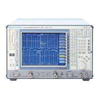
Rohde & Schwarz ZVRL Operating Manual (1017 pages)
VECTOR NETWORK ANALYZER
Brand:
Rohde & Schwarz
| Category:
Test Equipment
| Size: 6 MB
Table of Contents
Table of Contents
7
General Information
9
Manual for ZVR Family
9
Update Procedure
9
Initial Steps
9
Documentation of Firmware Modifications
9
1 Firmware Update
10
System Requirements
10
Preparations for Update
10
Contents of Firmware Update Kit
10
Update Procedure
10
2 New Features, Improvements and Modifications
13
New Features
13
Improvements
14
Modifications
14
3 Bug Fixes
15
4 Extensions to Operating Manual
16
5 New IEEE-Bus Commands
28
6 Special Features
36
Preparation for Use
37
1 Preparation for Use
76
Introduction
76
Legend for Front and Rear View
76
Front View ZVR
76
Front View ZVR, ZVK and ZVM
76
Fig. 1-1 Front View ZVR
77
Front View ZVK, ZVM
88
Fig. 1-1 Front View ZVK, ZVM
88
Rear View ZVR, ZVK and ZVM
90
Fig. 1-2 Rear View
90
Instrument Setup
95
Stand-Alone Operation
95
Start-Up
95
Unpacking the Instrument
95
19" Rack Installation
96
AC Power Line Fuses
96
Connecting to AC Power
96
EMI Protection Measures
96
Battery-Powered Memory
97
Controller Function
98
Connecting a Mouse
100
Connecting an External Keyboard
100
Connecting an External Monitor
101
Connecting an Output Device
103
Connecting a CD-ROM Drive
110
Firmware Update
112
Installing Windows NT Software
113
1Option FSE-B17 - Third IEC/IEEE Interface
114
Installing the Software
114
Options
114
Operation
117
2Option FSE-B16 - Ethernet Adapter
118
Hardware Installation
118
Software Installation
119
Operation
123
2 Manual Operation
130
Introduction: Measurement Examples and Processing of Measured Values
130
Connection of the DUT
131
Measurement Task
131
Preset
131
Transmission Measurements - Measurement of Gain and Loss
131
Setting the Analyzer
132
Fig. 2-1 Measurement Display Screen with an Autoscaled Trace
134
Instrument Calibration
137
Performing the Measurement
138
Output of Measurement Results
140
Connection of the DUT
141
Measurement Task
141
Preset
141
Reflection Measurements
141
Setting the Analyzer
141
Instrument Calibration
142
Performing the Measurement
143
Fig. 2-6 Display of Phase in Cartesian Coordinates
144
Filter Measurements Measurements of Bandwidth, Q Factor and Shape Factor
146
Measurement of the Filter Parameters
146
Measurement Task
146
Reset, Setting and Calibration of the Instrument
146
Fig. 2-8 Determination of the 3 Db Bandwidth of a Bandpass
148
Processing of Measured Values
151
Menu Overview
154
SYSTEM Key Group
154
COPY Key Group
158
MEMORY Key Group
159
USER Key
161
SWEEP Key Group
162
MARKER Key Group
164
LINES Key Group
166
RESPONSE Key Group
167
CAL Key Group
170
Basic Steps of Operation
177
Screen
177
Fig. 2-12 General Setup of the Screen
177
The Diagram Area
178
The Softkey Area
188
Single Channel
189
Subdivision of Screen - Display Modes
189
Dual Channel Overlay Overlay
190
Dual Channel Split
190
Quad Channel Dual Split
191
Quad Channel Overlay
191
Full Screen - Expand Mode
192
Quad Channel Quad Split
192
Cartesian Diagrams
193
Diagrams
193
Fig. 2-14 Linear, Cartesian Diagram
193
Fig. 2-15 Cartesian Diagram with Two Segments on the Abscissa and Ordinate (Single Channel), each with Limit Lines and FAIL Message
194
Polar Diagrams
197
Fig. 2-18 Lin./ Log. Polar Diagram with 2 Segments (Single Channel)
199
Smith Charts
200
Fig. 2-19 Smith Chart
200
Charter Diagrams
201
Inverted Smith Charts
201
Fig. 2-20 Example of a Charter Diagram
201
Display Windows
202
Markers and Marker Info Lists
202
Message Fields
202
System Messages
205
Scale Reference Fields
206
Calling and Changing the Menus
208
Numeric Keypad - DATA ENTRY Key Group
210
Setting the Parameters
210
Roll-Key and Cursor Keys
211
Selection of Parameters
212
Editing of Numeric Parameters
217
Editing with External Keyboard
220
Editing with Auxiliary Line Editor
221
Disabling the Control Elements - HOLD Key
222
Mouse and External Keyboard Control
223
Setting the Step Size - STEP Key
223
External Keyboard
224
Mouse Control of Data Entry Windows and Tables
224
Mouse Control of Display Elements
225
General Configuration - SYSTEM Key Group
226
Selection of the Operating Mode - MODE Key
226
Time Domain Transformation (Option ZVR-B2)
227
Selecting the Gate
228
Switchover between Frequency and Time Domain
228
Selecting the Transformation Type
235
Defining the Frequency Grid
237
Scaling the Abscissa
242
Positioning the Gate
243
External Measurements
244
Measurements on Frequency-Converting Duts (Option ZVR-B4)
246
Harmonics Measurements
247
Mixer Measurements
248
Arbitrary Frequency Conversion
252
Fig. 2-22 Configuration of System Frequencies
252
Nonlinear Measurements (Option ZVR-B5)
255
Compression Point Measurement
256
Measurement of the
261
Nd and
261
Sweep Modes
267
Fast Measurement (FAST MODE)
269
Reference Channel Ports (Option ZVR-B6)
269
Preliminary Setup and Interface Configuration - SETUP Key
270
IEC Bus Address Selection
271
Programming the Interface Configuration and Time
271
User Port Configuration
272
Serial Interface Configuration
273
Fig. 2-24 Setting the Parameters for External Interfaces
273
Connecting the External Monitor
276
Setting Date and Time
276
External Reference Oscillator
277
Indication of the Automatic System Error Calibration
277
Enabling Firmware Options
278
Service Functions
279
Firmware Versions
280
Instrument Status and Measurement Parameters - INFO Key
280
Hardware Configuration and Options
281
System Messages
282
Fig. 2-26 System Messages
283
Measurement Documentation - COPY Key Group
284
Printing Data - COPY Key
284
Printing Configuration - SETTING Key
286
Selection of Displayed Elements
287
Selection of Data Medium
288
Selection of Hardcopy Format
288
Entry of Comment Text
289
Color Settings
290
Selection and Configuration of the Output Device
291
Selection of Line Style
293
Saving and Recalling Data Sets - MEMORY Key Group
294
Configuration of Memory - CONFIG Key
296
Saving Data Sets - SAVE Key
298
Selecting the Data Set for Storage
299
Selecting the Data Subset for Storage
301
Fig. 2-30 Selecting the Data Set for Storage
301
Configuration of ASCII Files
302
Recalling Data Sets - RECALL Key
306
Selecting the Data Set to be Recalled
307
Selecting Data Subsets to be Recalled
309
Fig. 2-32 Selecting Partial Data Sets to be Recalled
309
Switchover to Manual Operation and Default Setup - STATUS Group
311
Switchover to Manual Operation - LOCAL Key
311
Default Setup - PRESET Key
312
Macros - USER Key
314
Fundamentals
314
Starting Macros
315
Defining Macros
316
Defining the Sweep Range - STIMULUS Key Group
318
Sweep Setup - SWEEP Key Group
320
1Settings for the Sweep Variable - SWEEP Key
320
Single Point Measurement
321
Defining the Grid
322
Fig. 2-33 Editing the Segment List
323
Defining the Number of Points
328
Setting the Trigger Mode
329
Automatic or Manual Setting of the Sweep Time
332
Coupling of Display Channels
333
Miscellaneous Settings
334
2Starting a New Sweep - RESTART Key
335
3Setting Fixed Sweep Parameters - SOURCE Key
336
4Setting the Averaging Function and the Receiver Bandwidth - AVG Key
341
The Marker Functions - MARKER Key Group
344
1Main Markers - MARKER Key
344
Switching on and Moving Markers
346
Conversion of the Marker Value
347
Format of the Marker Value
348
Info List and Interpolation
351
2Marker Search Functions - SEARCH Key
352
3Delta Markers - DELTA Key
356
4Marker Assignment Functions - = MKR Key
358
Display and Limit Lines - LINES Key Group
360
1Display Lines - LINES Key
360
2Limit Lines - LIMITS Key
362
Selecting and Switching on Limit Lines
363
Defining a Limit Line in a Circular Diagram
365
Defining a Limit Line in a Cartesian Diagram
367
Moving a Limit Line
371
Display and Limit Check
373
Selection of Display Channel - CHANNEL Group
374
Configuring of Measured-Value Display - RESPONSE Key Group
376
1Selection of the Measured Quantity - MEAS Key
376
Measurement of S-Parameters
377
Measuring Wave Quantities
381
Measuring Ratios of Wave Quantities
381
Measurement of Two-Port Z or y Parameters
387
Converting the Measured Quantity
390
Measurement of Stability Factors
392
Measuring DC Voltage
393
2Formatting of the Measured Quantity - FORMAT Key
394
3Scaling of the Test Diagram - SCALE Key
401
4Selection of the Test Diagram - DIAGRAM Key
406
Defining the Cartesian Segmentation of the y Axis
408
Defining the Polar Radial Segmentation
412
5Configuration of the Screen - DISPLAY Key
414
Defining the Number and Arrangement of the Display Channels2.285
414
Expansion of Diagrams to Maximum Screen Format
415
Configuring the Graphic Elements of the Display
416
Fig. 2-38 Setting the Screen Colors
417
6Operations with Traces - TRACE Key
421
Correction of System Errors - CAL Key Group
427
1Calibration - CAL Key
427
Performing a System-Error Calibration
429
System Error Calibration
429
A)Specification of the Connectors at the Test Ports
430
B)System-Error Calibration Procedure
432
A)Tom Calibration Procedure
434
Full Two-Port Calibration (ZVR, ZVC, ZVK and ZVM)
434
B)Trm Calibration Procedure
436
C)Trl Calibration Procedure
438
D)Tna Calibration Procedure
440
F)Tom-X Calibration Procedure
443
G)Autokal Fundamental Calibration
444
Full Two-Port Calibration (ZVRE, ZVCE)
446
Automatic Two-Port Transfer Calibration
449
B)Autokal Fundamental Calibration
449
Full One-Port Calibration (ZVRL)
456
Unidirectional Two-Port Calibration (ZVRL)
460
Autokal Fundamental Calibration (ZVRL)
461
A)Transmission Normalization
462
B)Reflection Normalization
463
C)Combined Transmission and Reflection Normalization
465
1.11Normalization Calibration (ZVRL)
467
A)Transmission Normalization
467
B)Reflection Normalization
468
C)Combined Transmission and Reflection Normalization
469
Auxiliary Functions for System Error Calibration
470
Characteristics of Calibration Standards
472
Fig. 2-40 Selecting the Connector Families
473
Fig. 2-41 Modifying the Standards
477
Power Calibration (Option ZVR-B7)
484
Fig. 2-42 Entry of a Frequency-Dependent Calibration Factor
495
2Entry of Offset Parameters - OFFSET Key
500
Annex C: List of Commands
505
Remote Control
507
Introduction
542
Brief Instructions
542
Remote Control
542
Switchover to Remote Control
543
Remote Control Via IEC Bus
543
Indications During Remote Control
543
Setting the Device Address
543
Return to Manual Operation
544
Remote Control Via RS-232-Interface
544
Indications During Remote Control
544
Setting the Transmission Parameters
544
Remote Control Via RSIB Interface
545
Windows Environment
545
Indications During Remote Control
546
Return to Manual Operation
546
Unix Environment
546
Messages
547
IEC/IEEE Bus Interface Messages
547
RSIB Interface Messages
547
Device Messages (Commands and Device Responses)
548
Structure and Syntax of the Device Messages
549
SCPI Introduction
549
Structure of a Command
549
Structure of a Command Line
552
Responses to Queries
552
Parameters
553
Overview of Syntax Elements
554
Description of Commands
555
Notation
555
Common Commands
558
Calculate Subsystem
561
Calculate:filter - Subsystem
561
Calculate:format Subsystem
563
Calculate:gdaperture Subsystem
564
Calculate:limit Subsystem
565
Calculate:marker Subsystem
570
Calculate:math Subsystem
579
Calculate:smoothing Subsystem
580
Calculate:transform Subsystem
581
Calculate:unit Subsystem
584
Diagnostic Subsystem
585
Display Subsystem
586
Format Subsystem
593
Hcopy Subsystem
596
Initiate Subsystem
602
Input Subsystem
603
10Instrument Subsystem
604
11Mmemory Subsystem
605
12Output Subsystem
613
13Program - Subsystem
615
14Sense Subsystem
617
Sense:average Subsystem
617
Sense:bandwidth Subsystem
618
Sense:correction Subsystem
619
Sense:detector Subsystem
642
Sense:frequency Subsystem
643
Sense:function Subsystem
648
Sense:roscillator - Subsystem
650
Sense:segment Subsystem
651
Sense:sweep Subsystem
653
15Source Subsystem
655
16Status Subsystem
664
17System Subsystem
671
18Trace Subsystem
681
19Trigger-Subsystem
685
Instrument Model and Command Processing
687
Input Unit
687
Command Recognition
688
Data Set and Instrument Hardware
688
Status Reporting System
688
Output Unit
689
Command Sequence and Command Synchronization
689
Status Reporting System
690
Structure of an SCPI Status Register
690
Description of the Status Registers
693
Status Byte (STB) and Service Request Enable Register (SRE)
693
Event-Status Register (ESR) and Event-Status-Enable Register (ESE)
694
IST Flag and Parallel Poll Enable Register (PPE)
694
Status:operation Register
695
Status:questionable-Register
696
Status:questionable:limit Register
697
Application of the Status Reporting System
698
Serial Poll
698
Service Request, Making Use of the Hierarchy Structure
698
Error-Queue Query
699
Parallel Poll
699
Query by Means of Commands
699
Reset Values of the Status Reporting System
700
Softkeys and Related IEC/IEEE BUS Commands
701
SYSTEM Key Group
701
COPY Key Group
707
MEMORY Key Group
708
STATUS Key Group
710
STIMULUS Key Group
711
SWEEP Key Group
711
MARKER Key Group
714
Maintenance and Troubleshooting
730
Maintenance
730
Mechanical Maintenance
730
Electrical Maintenance
730
Testing the Frequency Accuracy
730
Testing the Generator Level
730
Testing the Receiver Accuracy
730
Verifying the Measuring Accuracy
730
Monitoring the Function
731
Switch-On Test
731
Monitoring the Synthesizers and the Level Control
731
Synthesizer Error Messages
731
Error Message of Level Control
731
Overload Displays
731
Function Description of the Complete Instrument
732
Description of the Analog Modules
732
Test Set
732
Converter
733
Front End
733
Synthesizer
733
Local
734
Output Stage
734
Source
734
Modules of the Digital Unit
734
Processor Structure
735
Measurement Control Unit
735
Self Test
736
Testing the Rated Specifications
738
Measuring Instruments and Accessories (ZVR, ZVRE, ZVRL)
738
Test Sequence (ZVR, ZVRE, ZVRL)
739
Testing the Generator Specifications
739
Frequency Accuracy
739
Harmonics Suppression
739
Spurious Suppression
740
Phase Noise
741
Level Accuracy
742
Residual FM
742
Level Linearity
743
Matching to Output A1
744
Testing the Receiver Specifications
745
Absolute Accuracy
745
Linearity
746
Noise Level
747
Matching Input B1 and Input B2
748
Testing the Test Set Specifications
750
Matching to PORT1 and PORT2
750
Directivity
751
Testing the Attenuators
752
Crosstalk
753
Performance Test Report (ZVR, ZVRE, ZVRL)
754
Measuring Instruments and Accessories (ZVC, ZVCE)
778
Test Sequence (ZVC, ZVCE)
779
Testing the Generator Specifications
779
Frequency Accuracy
779
Harmonics Suppression
779
Spurious Suppression
780
Phase Noise
781
Level Accuracy
782
Residual FM
782
Level Linearity
783
Matching to Output A1
784
Testing the Receiver Specifications
785
Absolute Accuracy
785
Linearity
786
Noise Level
787
Matching Input B1 and Input B2
788
Testing the Test Set Specifications
790
Directivity
790
Matching to PORT1 and PORT2
790
Testing the Attenuators
791
Crosstalk
792
Performance Test Report (ZVC, ZVCE)
793
Checking of Rated Specifications
824
Measuring Equipment and Accessories (ZVM, ZVK)
824
Test Procedure (ZVM & ZVK)
825
Checking the Generator Specifications
825
Frequency Deviation
825
Harmonics
826
Spurious
827
Phase Noise
828
Residual FM
829
Level Accuracy
830
Level Linearity
831
Checking the Receiver Specifications
832
Absolute Accuracy
832
Linearity
833
Noise Level
834
Match Input B1 and Input B2
835
Checking the Test Set Specifications
836
Match at PORT1 and PORT2
836
Matching Reference Channel Inputs R1 and R2 Channel in
837
Raw Directivity
838
Checking the Attenuators
839
Dynamic Range
840
Performance Test Record (ZVM)
841
Performance Test Record (ZVK)
893
Advertisement
Advertisement
Related Products
Rohde & Schwarz ZVRE
Rohde & Schwarz ZVR
Rohde & Schwarz ZVK
Rohde & Schwarz ZVC
Rohde & Schwarz ZVCE
Rohde & Schwarz ZV-Z58
Rohde & Schwarz ZV-Z59
Rohde & Schwarz ZV-Z129
Rohde & Schwarz ZV-Z135
Rohde & Schwarz ZV-Z170
Rohde & Schwarz Categories
Measuring Instruments
Test Equipment
Portable Generator
Power Supply
Accessories
More Rohde & Schwarz Manuals
Login
Sign In
OR
Sign in with Facebook
Sign in with Google
Upload manual
Upload from disk
Upload from URL