Sign In
Upload
Manuals
Brands
Rohde & Schwarz Manuals
Portable Generator
SMCVB-K980
Rohde & Schwarz SMCVB-K980 Manuals
Manuals and User Guides for Rohde & Schwarz SMCVB-K980. We have
1
Rohde & Schwarz SMCVB-K980 manual available for free PDF download: User Manual
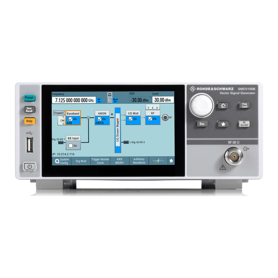
Rohde & Schwarz SMCVB-K980 User Manual (913 pages)
Vector Signal Generator
Brand:
Rohde & Schwarz
| Category:
Portable Generator
| Size: 21 MB
Table of Contents
Table of Contents
3
Safety Instructions
15
Safety and Regulatory Information
15
Labels on R&S SMCV100B
17
Warning Messages in the Documentation
18
Where to Find Key Documents on Rohde & Schwarz
18
Korea Certification Class B
18
Welcome
20
Key Features
20
Getting Started Manual
21
User Manuals and Help
21
Documentation Overview
21
What's New
21
Service Manual
22
Instrument Security Procedures
22
Printed Safety Instructions
22
Data Sheets and Brochures
22
Release Notes and Open Source Acknowledgment (OSA)
22
Application Notes, Application Cards, White Papers, Etc
23
Videos
23
Getting Started
24
Preparing for Use
24
Lifting and Carrying
24
Unpacking and Checking
24
Choosing the Operating Site
24
Setting up the R&S SMCV100B
25
Considerations for Test Setup
26
Connecting to Power
27
Connecting to LAN
27
Connecting a Monitor
28
Connecting USB Devices
29
Connecting to RF Coaxial Connectors
29
Connecting to RF 50 Ω
31
Connecting to Ref In/Ref out
31
Connecting to Dig. IQ HS X
31
Connecting to IP Data
32
Switching on or off
34
Front Panel Tour
35
Instrument Tour
35
Rear Panel Tour
39
Trying out the Instrument
42
Generating an Unmodulated Carrier
43
Generating a Digitally Modulated Signal
44
Triggering the Instrument with an External Signal
47
Enabling and Configuring a Marker Signal
51
Verifying the Generated Signal with the Graphics Display
53
Saving and Recalling Settings
56
Generating a DAB Signal
58
System Overview
60
Brief Introduction to the Instrument's Concept
60
Signal Flow at a Glance
61
Internal Baseband Source ("Baseband" Block)
62
Digital Baseband Input/Output ("BB Input"/ "I/Q Digital" Block)
62
Additional White Gaussian Noise ("AWGN" Block)
63
I/Q Stream Mapper" Block
63
I/Q Modulator ("I/Q Mod" Block)
63
RF ("RF" Block)
63
Applications Examples of the R&S SMCV100B
63
Instrument Control
64
Means of Manual Interaction
64
Possible Ways to Operate the Instrument
64
Understanding the Display Information
65
Accessing the Functionality
70
Entering Data
71
Getting Information and Help
72
Remote Control
74
Remote Operation over VNC
74
Vnc
74
Configuring Internal Baseband Signals
75
Overview of the Signal Generation Modes
75
Accessing the Functions in the Baseband Domain
76
Generating Signals According to Broadcast Standards
77
Basics on Signals, Modulation Types and Filters
80
Common Functions and Settings in the Baseband Domain
80
Common Settings
100
About the Custom Digital Modulation
106
Generating Custom Digital Modulated Signals
106
Required Options
106
Custom Digital Modulation Settings
107
General Settings
107
Settings
107
Data Source
110
Trigger, Marker and Clock Settings
110
Modulation Settings
112
Filter Settings
114
Power Ramp Control Settings
116
Data List Editor
118
Control and Marker Lists Editor
120
How to Create Data and Control Lists
124
References
127
Required Options
137
Using the Arbitrary Waveform Generator (ARB)
137
About ARB
138
ARB Settings
143
Settings: State
144
Load Waveform/File
145
Waveform Info
145
Clock Frequency
146
Create Multi Segment
146
HDD Streaming
146
Create Multi Carrier
147
Create Test Signal
147
Test Signal Form
147
How to Create, Generate and Play Waveform Files
152
How to Work with Waveform Libraries
168
How to Stream Waveforms from an External Storage Device
171
Tags for Waveforms, Data and Control Lists
173
Example: {Date: 2009-04-02;14:32:12}
176
CLOCK: Frequency
177
CONTROL LENGTH: Controllength
177
EMPTYTAG-Length: #Emptysequence
178
LEVEL OFFS: Rmsoffset_Db,Peakoffset_Db
179
Marker Mode [#]: Generator
180
SAMPLES: Samples
180
BURST LIST [#]: Pos0:State0; Pos1:State1
181
CW MODE LIST [#]: Pos0:State0; Pos1:State1
181
HOP LIST [#]: Pos0:State0; Pos1:State1
181
LEVATT LIST [#]: Pos0:State0; Pos1:State1
181
MAP LIST [#]: Pos0:State0; Pos1:State1
181
MARKER LIST [#]: Pos0:State0; Pos1:State1
181
[TRACE] LIST [#]: Pos0:State0; Pos1:State1
181
WAVEFORM-Length: #I0Q0I1Q1
182
MWV_SEGMENT_COUNT: Numofseg
183
MWV_SEGMENT_DURATION: Segdur0, Segdur1
183
MWV_SEGMENT_LENGTH: Samplesseg0, Samplesseg1
183
MWV_SEGMENT_CLOCK: Clockseg0, Clockseg1
184
MWV_SEGMENT_CLOCK_MODE: Mode
184
Mwv_Segment_Start
184
Samplestartoffsetseg0, Samplestartoffsetseg1
184
MWV_SEGMENT_LEVEL_MODE: Mode
185
Mwv_Segment_Level_Offs
185
Rmsoffs_Dbsg0,Peakoffs_Dbsg0
185
MWV_SEGMENT_SETTINGS_FILE: Segsettingfilepath
186
Generating Multi-Segment Waveform Files
190
Reducing the Crest Factor
190
About the Multi-Segment Waveforms
191
Required Options
191
Multi-Segment Settings
196
How to Create and Work with Multi-Segment Waveform Files
212
Reference to Triggering of Multi-Segment Waveforms
217
Generating Multi-Carrier Signals
220
About the Multi-Carrier Waveforms
221
Required Options
221
Multi-Carrier Settings
223
Section 6
224
Set to Default
224
Mode
225
Number of Carriers
225
Save/Recall Frame
225
Carrier Spacing
226
Clipping
226
Crest Factor Mode
226
Frequency
226
Target Crest Factor
226
Power Reference
227
Signal Period
227
Signal Period Mode
227
Clock Rate
229
Create/Create and Load
229
File Size
229
Output File
229
Output Settings
229
How to Use the Multi-Carrier Function
235
Fm/Phim/Am Configuration and Settings
238
Generating Fm/Phim/Am/Pulse Modulation Signals
238
Pulse Modulation Configuration and Settings
242
About Baseband Offsets
244
Shifting and Boosting the Baseband Signal
244
Baseband Offsets Settings
247
How to Improve Signal Characteristics by Shifting the Baseband Signal
248
Configuring External Baseband Signals
249
Overview of the Input and Output Signals and Interfaces
249
Overview of the Baseband and RF Output Signals
250
Overview of the Baseband Signal Sources
250
Important Signal Parameters and Interface's Characteristics
251
Interdependencies
251
I/Q Stream Mapper Settings
254
System Configuration Settings
254
External RF and I/Q Settings
255
Section 7
256
Auto Connect
257
Connect/Disconnect All Remote
257
Display
257
Connector Name
258
Direction
258
External Instrument
258
Preset Behavior: Keep Connections to External Instruments
258
I/Q Connection
259
Instrument Name
259
Remote Connection Status
259
Overview
266
Digital Baseband Input Settings
267
General Settings
269
Signal Input Settings
270
I/Q Digital Output Settings
272
General Settings
273
Channels Settings
275
Signal Output Settings
277
Generating Time-Aligned Baseband Signals
278
Triggering Several Instruments with a Common Trigger Signal
278
About the AWGN Generator
280
Adding Noise to and Impairing the Signal
280
Adding Noise to the Signal
280
Required Options
280
AWGN Block
284
AWGN Settings
285
[:Source
287
Bit Rate
288
Reference Mode
288
Set Noise Power Via
288
Show Powers for Output
288
Carrier Power, Signal Power
289
Carrier/Noise Ratio, Signal/Noise Ratio
289
E B /N
289
Noise Power (System Bandwidth), Interferer Power
290
Noise Power (Total Bandwidth)
291
How to Configure the Noise Generator for Receiver Tests
292
About the Linear I/Q Impairments
294
Impairing the Signal
294
Required Options
294
Digital Impairments Settings
296
About the I/Q Modulator
298
Applying I/Q Vector Modulation
298
I/Q Modulator Settings
298
Required Options
298
Optimizing I/Q Modulation Performance
301
Configuring the RF Signal
302
How to Access the RF Settings
303
How to Activate the RF Signal Output
303
Required Options
303
How to Set the Frequency and Level
304
RF Frequency Settings
306
RF Level Settings
308
RF Phase Settings
311
Reference Frequency Settings
312
Reference Oscillator
312
Required Options
312
Reference Output Settings
315
Adjustment Settings
316
Varying the RF Signal in List or Sweep Mode
317
Signal Generation and Triggering in the Sweep and List Modes
318
About Sweep Mode
326
About List Mode
329
Significant Parameters and Functions
330
Sweep Mode Settings
333
List Mode Settings
341
List Editor
347
How to Generate a Signal in List or Sweep Mode
351
Improving Level Performance
352
Attenuator
353
User Correction
355
Using Power Sensors
367
To Calibrate the Power Level with an R&S NRP Power Sensor
383
Configuring a Multi-Instrument Setup
387
Connecting to R&S SMW
387
Synchronizing Instruments
387
Configuring the Setup
389
Multi-Instrument Settings
392
About the Graphical Signal Display
394
Displaying Baseband Signal Characteristics in Real-Time
394
Monitoring Signal Characteristics
394
Required Options
394
Graphics Configuration Settings
401
Graphical Signal Display Settings
405
How to Verify the Generated Signal with the Graphics Display
406
About the File System
413
File and Data Management
413
Restoring the (Default) Instrument Configuration
416
How to Identify Parameters Which Are Not in a Preset State
418
Preset, Set to Default and Factory Preset Settings
418
How to Recall User Settings Automatically after Preset
419
Protecting Data
420
Reference
420
Saving and Recalling Instrument Settings
421
Save/Recall Settings
422
How to Save and Recall Instrument Settings
425
Accessing Files with User Data
426
File Select Settings
426
Exporting and Importing Remote Command Lists
428
Loading, Importing and Exporting Lists
428
Using the File Manager
428
File Manager Settings
429
Map Network Share Settings
430
How to Display All Saved Files
432
How to Map a Network Folder
432
How to Transfer Files from and to the Instrument
434
Removing File System Protection
435
Accessing the File System of the R&S SMCV100B over FTP
436
Accessing the R&S SMCV100B File System Using SMB (Samba)
437
Using a File Server for Test Files Exchange
439
Using a USB Storage Device for File Transfer
439
Creating Screenshots of Current Settings
440
Hardcopy Settings
440
How to Save a Hardcopy of the Display
443
Customizing the User Interface
444
General Instrument Functions
444
Display and Keyboard Settings
445
Display Update Settings
446
Defining the RF Signal State on Power on
447
How to Set the Initial Instrument Settings
448
About Global Connectors
449
Configuring Global Connectors
449
Required Options
449
Trigger Marker Clock Settings
451
RF Connectors Settings
453
Global Connectors Settings
454
How to Enable Signals and Perform Signal to Connector Mapping
457
Checking Parameters and Dependencies
458
Organizing Frequently Used Settings as Favorites
460
User Menu Settings
461
How to Use the User Menu for Fast Adjustments
462
Define User Key Actions Settings
464
How to Assign Actions to the [★ (User)] Key
465
Manage License Keys Settings
466
Managing Licenses and License Keys
466
Using the License Server
470
How to Move a Portable License
479
Using the Security Settings
481
Protection Level Settings
482
Setting Security Parameters
483
Configuring LAN Services
488
Password Management
491
How to Prevent Unauthorized Access
493
Undoing or Restoring Actions
496
Shutting down and Rebooting the Instrument
498
Network Operation and Remote Control
499
Overview of Remote Access Modes
500
Remote Control Interfaces and Protocols
501
LAN Interface
502
LXI Browser Interface
503
Remote Control Programs and Libraries
504
Hierarchy of the Status Registers
507
Status Reporting System
507
Structure of a SCPI Status Register
509
Status Byte (STB) and Service Request Enable Register (SRE)
511
Event Status Register (ESR) and Event Status Enable Register (ESE)
512
Application of the Status Reporting System
513
Operation Status Register (Status:operation)
513
Questionable Status Register (Status:questionable)
513
Reset Values of the Status Reporting System
515
Remote Access Settings
516
Network Settings
518
VISA Resource Strings
521
Instrument Emulations Settings
522
Remote Connections Settings
523
HUMS Settings
525
HUMS Enhanced Settings
527
QR Code
535
LXI Settings
536
LXI Status Settings
536
LXI Browser Settings
537
To Configure the Instrument for Remote Access
543
To Find the VISA Resource String
543
To Configure the Accces over LAN
544
To Establish a Remote Control Session over LAN
547
To Establish the Connection Using VXI-11 Protocol
548
To Establish the Connection with the LXI Web Browser
548
To Establish the Connection Using Socket Communication
553
To Trace Messages with the LXI Web Browser Interface
554
To Automate Tasks with Remote Command Scripts
555
To Return to Manual Operation
555
Displaying an SCPI List
558
Show SCPI Command
558
SCPI Recording Export Settings
559
How to Record / Create SCPI Lists
560
How to Convert and Save SCPI Lists
563
How to Find out the SCPI Commands for GUI Functions
564
How to Enable the VNC Service
565
To Operate the Instrument Using VNC
565
How to Set up Remote Operation from a Desktop System
566
How to Set up Remote Operation from a Smart Device
568
Code Generator Templates
571
LXI Functionality
571
References
571
Remote Control States
573
Conventions Used in SCPI Command Descriptions
574
Remote Control Commands
574
Common Commands
575
Programming Examples
575
Preset Commands
580
Mmemory Subsystem
581
File Naming Conventions
582
Accessing Files in the Default or in a Specified Directory
583
Programming Examples
584
Remote Control Commands
586
Calibration Subsystem
592
Diagnostic Subsystem
596
HUMS Remote Control Commands
599
Display Subsystem
606
Format Subsystem
611
Hcopy Subsystem
612
Hard Copy Settings
613
Automatic Naming
615
Kboard Subsystem
617
Output Subsystem
618
Sense, READ, Initiate and Slist Subsystems
621
Sconfiguration Subsystem
635
Multi Instrument Configuration
638
I/Q Stream Mapping
639
External RF and I/Q Instruments
640
Connector Settings
649
Source Subsystem
649
Source:bbin Subsystem
653
Source:bb Subsystem
660
Source:correction Subsystem
751
Source:frequency Subsystem
759
Source:input Subsystem
765
Source:iq Subsystem
765
Source:iq:output Subsystem
766
Source:list Subsystem
771
Source:phase Subsystem
784
Source:power Subsystem
785
Advertisement
Advertisement
Related Products
Rohde & Schwarz SMCVB-KB106
Rohde & Schwarz SMCVB-K31
Rohde & Schwarz SMCVB-K198
Rohde & Schwarz SMCVB-K199
Rohde & Schwarz SMCVB-K505
Rohde & Schwarz SMCVB-K522
Rohde & Schwarz SMCVB-K523
Rohde & Schwarz SMCVB-K547
Rohde & Schwarz SMCVB-K167 DVB-S
Rohde & Schwarz SMCVB-K167 DVB-S2
Rohde & Schwarz Categories
Measuring Instruments
Test Equipment
Portable Generator
Power Supply
Accessories
More Rohde & Schwarz Manuals
Login
Sign In
OR
Sign in with Facebook
Sign in with Google
Upload manual
Upload from disk
Upload from URL